PLC UV sensors & VIS sensors
The PLC UV sensors and VIS sensors serve as precision sensors for the measurement of UV irradiances and illuminances in systems with programmable logic controllers (PLCs). Available are spectral ranges from UVC (200–280 nm) to VIS (380–780 nm), three measuring ranges from 0–100 mW/cm² to 0–5000 mW/cm² and the output signals 4–20 mA, 0–10 V or 0–2 V. The built-in diffusers provide the required cosine correction.
The integrated electronics generate a signal voltage that is transmitted with the low interference cable to the PLC. The sensors are calibrated with traceability to the PTB (Physikalisch Technische Bundesanstalt, the German national test authority); after being calibrated, they are shipped with a factory calibration certificate.
For special applications, the sensors are available and with customer-specific measurement and spectral ranges.
For small control tasks, the PLC sensors can be connected to an RM-32 panel meter. The RM-32 shows the current irradiance on a 3.5-digit digital display and switches two relay contacts with adjustable warning and alarm signals.
To protect the sensor against contamination and aging (at extremely high irradiance and periodic reference measurements) we recommend our shutter.
Applications of PLC UV sensors and VIS sensors
- Sensors in PLC systems
- Control of UV LEDs and spotlights
- Precise measurement of irradiance and illuminance


| Product type | UV sensor: UV sensors with 4–20 mA, 0–10 V or 0–2 V output for controllers |
| Spectral range | UVC 200–280 nm, UVB 280–315 nm, UVA 315–400 nm, UVA+ 330–455 nm, UVBB 230–400 nm, VISB 400–480 nm, VIS 380–780 nm |
| Measuring range | 0–100 mW/cm²; 0–200 mW/cm²; 0–5000 mW/cm² |
| Calibration uncertainty (typ.) | 4.5–6.0 % (k = 2) |
| Output / interface | Output signal: 4–20 mA, 0–10 V, 0–2 V; Sensor connection: 5-pin, pluggable; Connection: M12, 5-pin |
| Time resolution | analogue sensor signal, determined by the instrument |
| Calibration | factory calibration, recalibratable |
| Standards / guidelines | no product-specific standard; calibration per DIN EN ISO/IEC 17025:2018 available |
| Suitable for | UV disinfection; UV curing and photopolymerisation; Automation and process integration; Packaging and filling technology |
| Not suitable for | spectrally resolved measurement (peak wavelength, bandwidth); irradiance above 5000 mW/cm² (standard range); sensor temperatures above 60 °C; use under water or under pressure |
| Datasheet revision | Rev. 2026-09-08 (e_plc.pdf) |
The calibration uncertainty stated above is the expanded uncertainty of the calibration (k = 2, confidence level approx. 95 %) and applies to the calibration source and the calibration conditions. In use the measurement uncertainty is larger: spectral mismatch at the source actually used, the sensor temperature, ageing since calibration as well as distance and alignment to the source are added to it. How these combine into an uncertainty budget is explained under Measurement uncertainty in UV measurement.
Highlights of PLC UV sensors and VIS sensors
- Direct PLC operation
- Selectable signal output
- Long-term stability
- Recalibratable sensors
- Integrated electronics
- Selectable measurement ranges
- Shutter optional
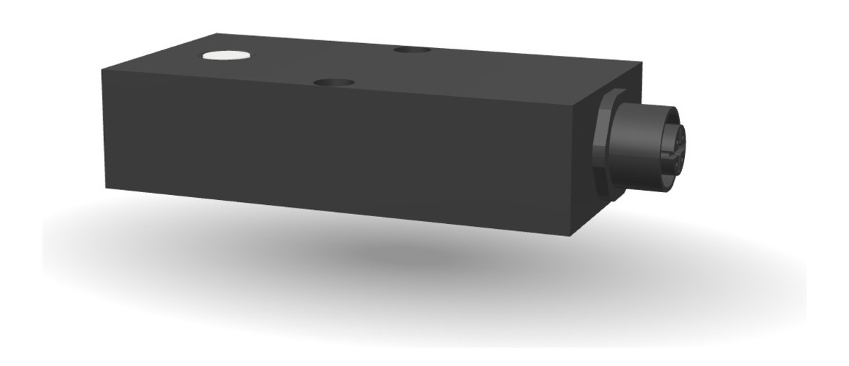
View the PLC sensor as a 3D model
Look at the sensor housing and its connectors from every side – directly in your browser.
The PLC sensor with analogue output signal can be viewed from all sides in the 3D product viewer – true to the original, generated from the CAD design data. Housing shape, connector and mounting dimensions can thus be examined in detail before planning.
Specifications of PLC UV sensors and VIS sensors
| Power supply | 24 V, 12 V, 5 V or ±5 V |
| Current input | < 15 mA |
| Signal output | 4 – 20 mA, 0–10 V, 0–2 V |
| Sensor connector | 5-pin, pluggable |
| Measuring range | 0–100 mW/cm² |
| 0–200 mW/cm² | |
| 0–5000 mW/cm² | |
| Dimensions | 80 × 40 × 20 mm |
| Weight | 150 g |
| Connector | M12, 5-pin |
| Operation temp. | 0 to 60 °C |
| Storage temp. | -10 to 60 °C |
| Humidity | < 80% Non-condensing |
Frequently asked questions: PLC sensors (analogue)
The sensor is connected via a five-pin M12 plug with shielded cable; the electronics are inside the sensor, so the cable can be extended without measuring errors. With 4–20 mA the measuring current flows via a two-wire loop to the analogue input of the controller, with 0–10 V or 0–2 V the voltage is measured against ground. The supply voltage is 24 V, 12 V, 5 V or ±5 V depending on the version, with a current consumption below 15 mA; the operating temperature is 0–60 °C.
In high-power applications, such as UV LED lamps with several W/cm², filter and diffuser age under continuous irradiation and become contaminated in dusty processes. The electronic shutter opens the sensor only for the measurement and protects it in between. This extends the calibration intervals in the machine, and the reading remains comparable over months. Without a shutter Opsytec recommends recalibration every 12 months.
0–10 V is the simplest solution for short runs inside the cabinet, but it reacts sensitively to cable length, voltage drop and interference. 4–20 mA is the industrial standard for long distances and noisy environments: the current stays constant over the cable length, and the live zero at 4 mA makes a broken wire distinguishable from a reading of zero. RS-485 and other digital interfaces transmit the value without D/A conversion, allow several sensors on one bus and carry status, serial number and calibration data along with the reading. For new connections with diagnostic requirements, digital is the first choice; 4–20 mA remains the most robust analogue compromise.
Seven spectral ranges: UVC 200–280 nm, UVB 280–315 nm, UVA 315–400 nm, UVA+ 330–455 nm, UVBB 230–400 nm, VISB 400–480 nm and VIS 380–780 nm with V(λ) weighting. Plus three measuring ranges: 0–100 mW/cm², 0–200 mW/cm² and 0–5000 mW/cm². Output signal, supply voltage and measuring range are chosen to suit the measuring task and the controller; customer-specific measuring and spectral ranges as well as special housings are possible.
With the RM-32 panel instrument, to which the PLC sensor is connected directly. It shows the current irradiance on a 3½-digit display and outputs adjustable warning and alarm signals via two relay contacts. For small control tasks that replaces the connection to a programmable logic controller entirely.
With an electronic shutter that exposes the sensor only for the measurement. This is advisable for periodic reference measurements and especially at extremely high irradiance, because both contamination and sensor ageing progress faster there. In general the sensors are calibrated traceably to the PTB, can be recalibrated, and are long-term stable through the choice of materials.
For an analogue input, the PLC sensor with 4–20 mA, 0–10 V or 0–2 V, supplied with 24 V, 12 V, 5 V or ±5 V and drawing under 15 mA. If the calibration status is to arrive alongside the reading, the PLC.D with RS-485 is the choice, and for Ethernet installations the PLC.net with Modbus TCP. The measuring range is selected from the source, not from the type of system: 0–100, 0–200 or 0–5000 mW/cm².
Yes, provided the reading arrives fast enough and unambiguously. The analogue PLC sensor delivers the scaled instantaneous value as 4–20 mA or 0–10 V to an analogue input; from it the controller adjusts lamp power, dimming value or feed rate. Control quality depends on the cycle: with a short irradiation zone and a high belt speed, too slow a sampling misses the maximum and underestimates the dose. A lower and an upper limit have to be defined for both irradiance and dose.
The calibration certificate states the expanded calibration uncertainty with k = 2; for the PLC sensors it is typically 4.5–6.0 %. In use the measurement uncertainty is larger, because spectral mismatch at the source actually used, sensor temperature, ageing and measuring geometry are added to it. How these combine into an uncertainty budget is explained under Measurement uncertainty in UV measurement.
Order numbers, scope of delivery, accessories and versions
The order number of a PLC sensor is made up of four digits: PLC [S][V][A][M]. Two examples:
- PLC1111 - UVC sensor, supply 24 V, output signal 0–10 V, measuring range 0–100 mW/cm²
- PLC3222 - UVA sensor, supply 12 V, output signal 0–2 V, measuring range 0–200 mW/cm²
Scope of delivery: the PLC sensor and the factory calibration certificate. Please state the required type with your order.
| Spectral range | Digit |
|---|---|
| UVC | 1 |
| UVB | 2 |
| UVA | 3 |
| VISB | 4 |
| LUX | 6 |
| UVA+ | 7 |
| UVBB | 8 |
| special version | 9 |
Position [S] of the order number PLC [S][V][A][M].
| Operating voltage | Digit |
|---|---|
| 24 V DC | 1 |
| 12 V DC | 2 |
| ±5 V DC | 3 |
| 5 V DC | 4 |
| special version | 9 |
Position [V] of the order number PLC [S][V][A][M].
| Output signal | Digit |
|---|---|
| 0–10 V | 1 |
| 0–2 V | 2 |
| 4–20 mA | 3 |
| special version | 9 |
Position [A] of the order number PLC [S][V][A][M].
| Measuring range | Digit |
|---|---|
| 0–100 mW/cm² | 1 |
| 0–200 mW/cm² | 2 |
| 0–5000 mW/cm² | 3 |
| special version | 9 |
Position [M] of the order number PLC [S][V][A][M].
| Length | Order number |
|---|---|
| Connecting cable, 2 m | 920310 |
| Connecting cable, 5 m | 920310-5 |
| Connecting cable, 10 m | 920310-10 |
| Length | Order number |
|---|---|
| Connecting cable, 2 m | 920310-I |
| Connecting cable, 5 m | 920310-I5 |
| Connecting cable, 10 m | 920310-I10 |
| Designation | Order number |
|---|---|
| Shutter | 860507 |
For periodic reference measurements the electrically driven shutter protects the sensor from soiling and - at very high irradiance - from ageing. Operation at 24 V, dimensions 130 x 80 x 75 mm.
| Version | Order number |
|---|---|
| RM-32, 230 V version | 670029 |
| RM-32, 110 V version | 670028 |
For small control tasks the PLC sensor can be operated on the panel meter RM-32: it shows the irradiance on a 3½-digit digital display and outputs adjustable warning and alarm signals through two relay contacts.
Connection and pin assignment
| Name | Wire colour | Connector PIN |
|---|---|---|
| GND / Shield | brown | PIN 1 |
| Supply 24 VDC | white | PIN 2 |
| not used | – | PIN 3 |
| Signal High 0 – 10 VDC | black | PIN 4 |
| Signal Low | grey | PIN 5 |
On versions with an open cable end there is no connector; the wire colours remain the same.
| Name | Wire colour | Connector PIN |
|---|---|---|
| GND / Shield | brown | PIN 1 |
| Supply 12 VDC | white | PIN 2 |
| not used | – | PIN 3 |
| Signal High 0 – 10 VDC | black | PIN 4 |
| Signal Low | grey | PIN 5 |
On versions with an open cable end there is no connector; the wire colours remain the same.
| Name | Wire colour | Connector PIN |
|---|---|---|
| Supply 24 VDC | brown | PIN 1 |
| Supply 24 VDC | white | PIN 2 |
| GND / Shield | blue | PIN 3 |
| GND / Shield | black | PIN 4 |
| not used | – | PIN 5 |
The sensor sits in the current loop: PIN 1 and PIN 2 carry the supply, PIN 3 and PIN 4 the return. The measuring instrument or PLC input is placed in the return line and reads the loop current. On versions with an open cable end there is no connector; the wire colours remain the same.
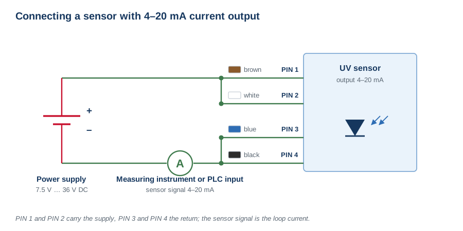
Connection in the current loop, supply 7.5 V to 36 V DC.
The connecting cables are available with an M12 female or an M12 male connector. Both diagrams show the mating face, so the contacts are mirrored with respect to each other. The keyway fixes the orientation.

M12 female connector, 5-pole – view onto the mating face.
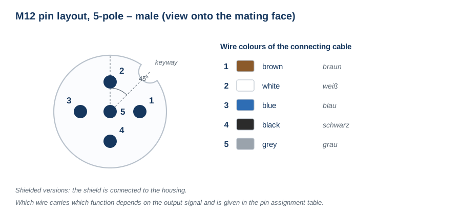
M12 male connector, 5-pole – view onto the mating face.