Radiometer sensors and UV measuring heads
Radiometer sensors extend the RMD, RM-12 and UV-MAT systems with defined spectral and measuring ranges. The appropriate measuring head is chosen from the source, the expected irradiance, the measuring geometry and the compatible display unit. The standard range comprises seven spectral ranges and four measuring ranges per sensor.
Spectral range, measuring range and cosine correction all sit in the measuring head; the display unit only reads out what arises there – the underlying measurement physics is covered under design and error sources of UV sensors.
System assignment
| Display unit | Matching measuring heads | Note |
|---|---|---|
| RMD and RMD Pro | Measuring heads with integrated memory for calibration and manufacturing date | Several heads in succession on one instrument; each head carries its own calibration certificate. |
| RM-12 | Measuring heads of the RM-12 series | Head and instrument form the calibrated pairing; technical data in the table below. |
| UV-MAT | Measuring heads for dose control | Selected by the spectral range of the process and the irradiance expected. |
The spectral and measuring ranges per model, together with the common technical data, are given in the tables below.
Calibration of the pairing
Each measuring head is calibrated individually and ships with a factory calibration certificate; traceability is to the PTB. What governs is the pairing of measuring head, display unit and calibration source: a head calibrated against a different lamp type reads systematically wrong at the new source. When changing to another source, check whether the existing calibration still applies – UV calibration describes the procedures and records.
Versions
- Seven spectral ranges and four measuring ranges per sensor
- Integrated electronics for low-noise signal transmission
- Integrated diffuser for cosine correction under non-perpendicular irradiation
- Sensors for assessing the biological effect of radiation
- Optionally splash-proof to IP65, in special housings or with extended measuring and spectral ranges
Repair and spare parts are handled under service and repair.
Which sensor suits UV LEDs from 365 to 405 nm and why the UVA+ range measures more reliably there is explained on the page Measuring UV LEDs.
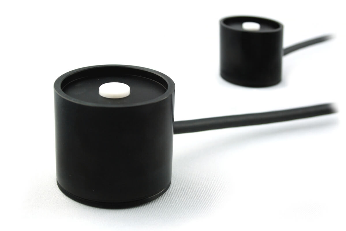


| Product type | UV sensor: measuring heads for RMD, RMD Touch and RM-12 in seven spectral ranges |
| Spectral range | UVC 200–280 nm, UVB 280–315 nm, UVA 315–400 nm, UVA+ 330–455 nm, UVBB 230–400 nm, VISB 400–480 nm, LUX 380–780 nm |
| Measuring range | 0–199 mW/cm²; 0–1999 mW/cm² (opt. -1); 0–19.9 W/cm² (opt. -2); 0–19.9 mW/cm² (opt. -3); 0–10 W/cm²; 0–1 W/cm² |
| Calibration uncertainty (typ.) | 4.5–6.0 % (k = 2) |
| Output / interface | Signal voltage: 0–2 V; sensor connector: M12 (5-pin) |
| Time resolution | analogue sensor signal, determined by the instrument |
| Calibration | traceable to PTB, factory calibration, ISO 17025 calibration optional (DIN EN ISO/IEC 17025:2018), recalibratable |
| Standards / guidelines | no product-specific standard; calibration per DIN EN ISO/IEC 17025:2018 available |
| Suitable for | Photobiology and biotechnology; Plants, agriculture and food; UV disinfection; UV curing and photopolymerisation |
| Not suitable for | spectrally resolved measurement (peak wavelength, bandwidth); irradiance above 10 W/cm² (standard range); sensor temperatures above 60 °C; use under water or under pressure |
| Datasheet revision | Rev. 2026-09-08 (e_radiometric_sensors.pdf) |
The calibration uncertainty stated above is the expanded uncertainty of the calibration (k = 2, confidence level approx. 95 %) and applies to the calibration source and the calibration conditions. In use the measurement uncertainty is larger: spectral mismatch at the source actually used, the sensor temperature, ageing since calibration as well as distance and alignment to the source are added to it. How these combine into an uncertainty budget is explained under Measurement uncertainty in UV measurement.
View the radiometer sensors as a 3D model
Look at the sensor heads from every side, rotate and zoom – directly in your browser.
The sensor heads for the RM and RMD UV radiometers can be viewed from all sides in the 3D product viewer – true to the original, generated from the CAD design data. Shape, connector and dimensions can thus be examined in detail before making a choice.
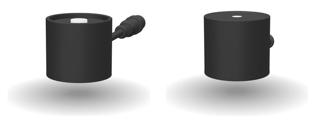
| UVC | 200–280 nm |
| UVB | 280–315 nm |
| UVA | 315–400 nm |
| UVA+ | 330–455 nm |
| UVBB | 230–400 nm |
| VISB | 400–480 nm |
| LUX | 380–780 nm, V(λ) |
| Supply voltage | ± 5 V |
| Signal voltage | 0–2 V |
| Sensor connector | M12 (5-pole) |
| Optical area | Ø 10 mm |
| Measuring range | 0–199 mW/cm² |
| 0–1999 mW/cm² (opt. -1) | |
| 0–19,9 W/cm² (opt. -2) | |
| 0–19,9 mW/cm² (opt. -3) |
| Spectral range | UVA, UVA+, UVBB |
| Measurement range, typ. | 0–10 W/cm² |
| Resolution | 0,001 µW/cm² |
| Spectral range | UVB, UVC, VISB |
| Measurement range, typ. | 0–1 W/cm² |
| Resolution | 0,001 µW/cm² |
| Spectral range | UVC (for proof of occupational safety), erythema + UVA |
| Measurement range, typ. | 0–10 mW/cm² |
| Resolution | 0,001 µW/cm² |
| Dose range | 0–100 MJ/cm² |
| Illumination meas. range | 0–500.000 lx |
| Resolution | 0,001 lux |
| Dynamic range | 1 : 10,000,000 |
| AD conversion | 24 bit |
| Temperature sensor | integrated |
| Dimensions | Ø 40 mm, h 35 mm |
| Optical area | Ø 6 mm |
| Weight | 160 g |
| Connecting cable | 2 m |
| Operation temperature | 0 to 60 °C |
| Storage temperature | -10 to 60 °C |
| Humidity | < 80% non-condensing |
| Calibration uncertainty (typ.) | 4.5–6.0 % (k = 2) |
| Linearity error | < 1 % |
| Aging / year | < 3 % |
| Temperature drift | < 0,1 %/°C |
Frequently asked questions: Radiometer sensors
Yes, but in two versions: the RMD digital sensors store their calibration data in the sensor and are recognised automatically by the RMD, RMD Pro and RMD Touch. The RM-12 sensors deliver an analogue signal of 0–2 V via the five-pin M12 connector. A sensor cannot be swapped between the two instrument classes, so the instrument must be stated when ordering. Both versions are available in the seven spectral ranges UVC, UVB, UVA, UVA+, UVBB, VISB and LUX.
The sensor heads measure 40 mm in diameter at 35 mm height and weigh about 150 g; the connecting cable is 2 m long. The optical surface sits behind a cosine-corrected diffuser, so the sensor is placed flat on the measuring plane or mounted on a tripod using the thread on the back. An IP65 version is optionally available for splash water; the operating temperature range is 0–60 °C.
The calibration certificate states the expanded calibration uncertainty with k = 2; for the radiometer sensors it is typically 4.5–6.0 %. In use the measurement uncertainty is larger, because spectral mismatch at the source actually used, sensor temperature, ageing and measuring geometry are added to it. How these combine into an uncertainty budget is explained under Measurement uncertainty in UV measurement.
Measuring head and radiometer: what has to match
A measuring head for a radiometer is not an accessory but half the instrument. Spectral range, measuring range and cosine correction sit in the head; the display unit only reads out what happens there.
That is why the heads are interchangeable and calibrated individually: an RMD with a UVC head measures something different from the same RMD with a UVA head – and each calibration has its own certificate.
Order numbers, scope of delivery, accessories and versions
| Spectral range | Order number |
|---|---|
| UVC | 811010 |
| UVB | 811020 |
| UVA | 811032 |
| UVA+ | 811047 |
| UVBB | 811012 |
| VISB | 811043 |
| LUX | 811061 |
These sensors are operated on the UV radiometer RM-12.
| Item | Value |
|---|---|
| Sensor connector | M12 (5-pole) |
| Measuring range | 0–199 mW/cm², 0–1999 mW/cm² (option -1) |
| Optical area | Ø 10 mm |
| Spectral range | Order number |
|---|---|
| UVC | 814410 |
| UVB | 814420 |
| UVA | 814432 |
| UVA+ | 814447 |
| UVBB | 814412 |
| VISB | 814443 |
| LUX | 814461 |
These sensors are fully digital and are operated on the RMD or RMD Pro.
| Item | Value |
|---|---|
| Measuring range, typ. | 0–10 W/cm² |
| Resolution | 0.001 µW/cm² |
| Dynamic range | up to 10⁷ |
| AD conversion | 24 bit |
| Temperature sensor | integrated |
| Optical area | Ø 6 mm |
| Designation | Order number |
|---|---|
| Sensor for the PLC | 760001 |
For operation on a machine control there is the sensor with an analogue output; the spectral range, the operating voltage, the output signal and the measuring range are set through the order key of the PLC sensors.
| Item | Value |
|---|---|
| Operating voltage | 24 V |
| Current consumption | < 15 mA |
| Output signal | 0–10 V |
| Connection | cable (2 m, optionally up to 10 m) |
Version with a current output:
| Item | Value |
|---|---|
| Operating voltage | 24 V |
| Output signal | 4–20 mA |
| Connection | cable (2 m, optionally up to 10 m); brown = +24 V DC, white = +24 V DC, black = 0 V, blue = 0 V |