Integrating spheres - for measurement and as homogeneous light sources
Integrating spheres distribute incident light by diffusing reflection evenly over the inner surface of the sphere. They are used for the integration of light and radiation and as a source of uniform diffuse radiation – for example for luminous flux and radiant flux measurements, laser power measurement, detector calibration and measurements of diffuse reflectance and transmittance. Opsytec manufactures them individually with diameters from 25 mm to 2.5 m and coatings of barium sulfate, PTFE or gold.
Highlights of our integrating spheres
- Specialized in customer-specific production
- Diameter of 25 mm to 2.5 m
- Barium sulfate, gold, and PTFE coatings to choose from
To avoid interfering fluorescence and measurement errors, especially at low luminous flux, our integrating spheres are made of gold or BaSO₄-coated metal spheres. The PTFE integrating spheres are manufactured as solid hollow spheres in a cylindrical aluminium housing.
Thus, we additionally ensure that for all integrating spheres no light comes from outside, as is possible with thin-walled plastic spheres.
Applications of integrating spheres
- Measurement of luminance and radiance of lamps
- Laser power measurement
- Measurement of LEDs, OLEDs, displays, light guides
- Detector calibration
- Measurement of diffuse reflection and transmission
- Uniform light source
In laser metrology the same arrangement is called an energy detector or power detector with an integrating sphere: the sphere accepts the beam, distributes it over the inner surface and thereby makes it measurable with a single detector – regardless of where the beam enters and how it is profiled.
How the luminous flux and radiant flux of LEDs are measured with an integrating sphere and spectroradiometer is described on the page Measuring the luminous flux of LEDs.
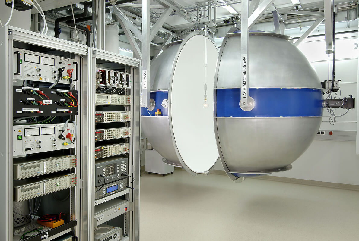
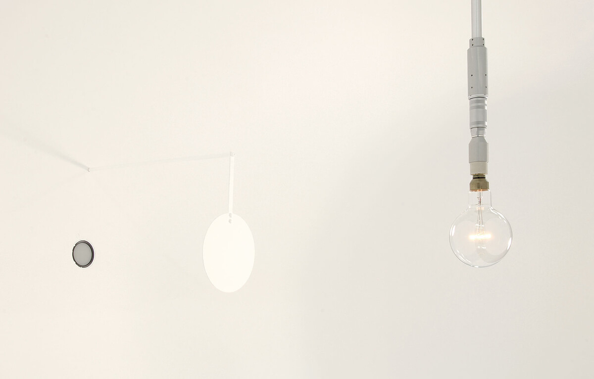

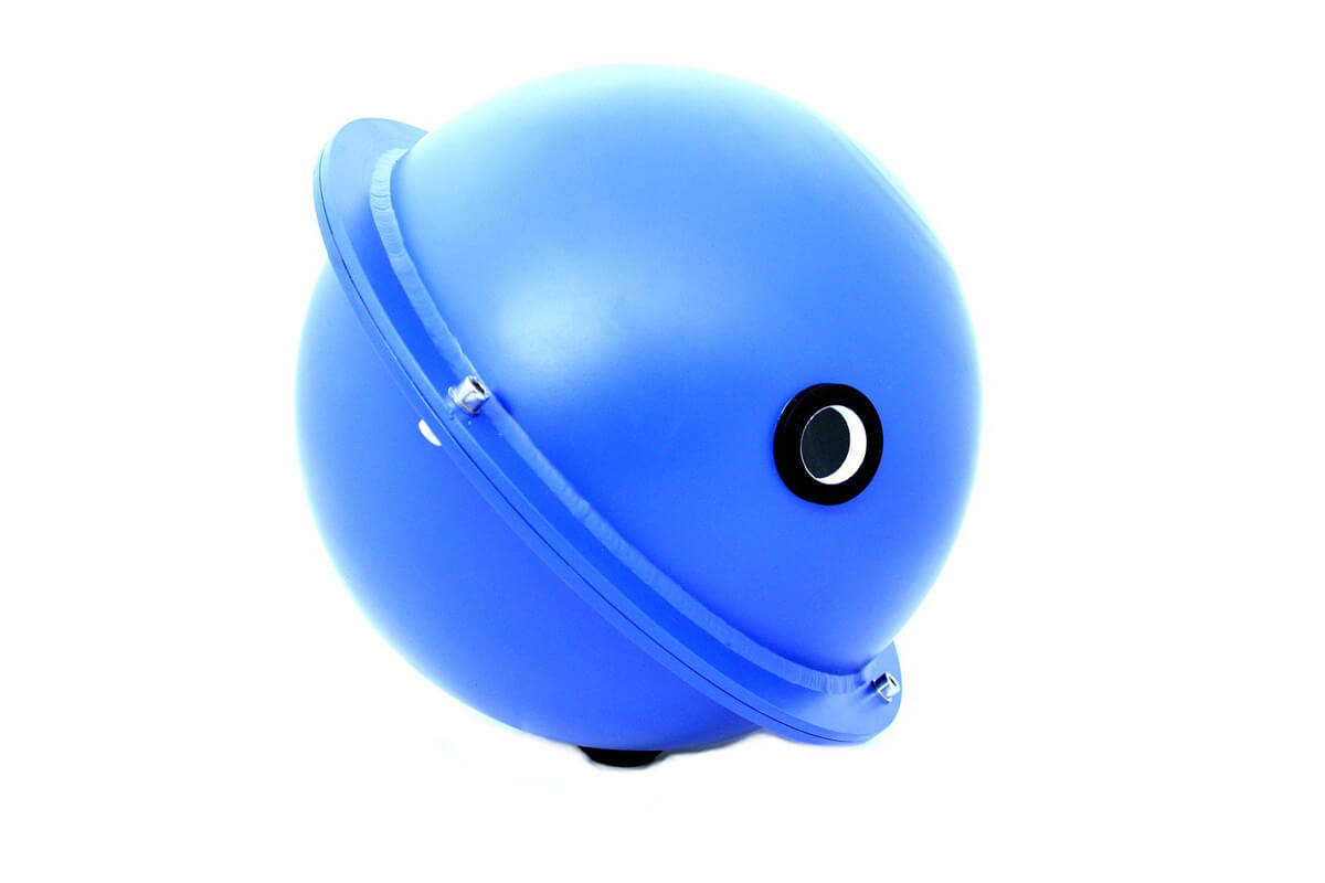

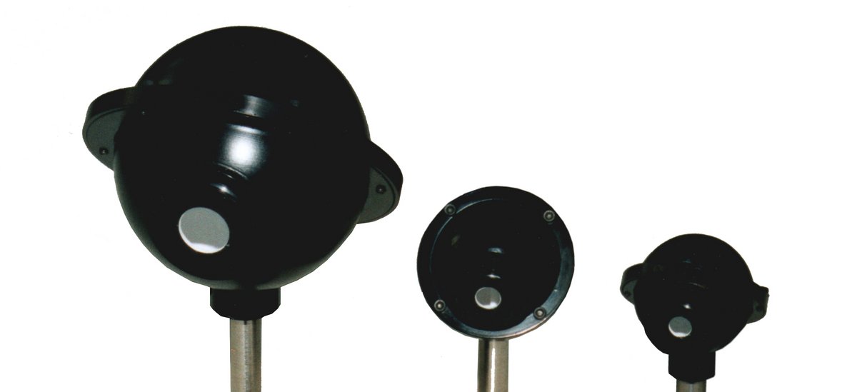
How an integrating sphere works: multiple reflection and sphere multiplier
The diffusely reflecting inner surface emits according to Lambert's law: every illuminated point gives the light off equally in all directions. Together with the spherical geometry this produces a property no other shape delivers – the illuminance on the wall depends neither on where the light enters nor on which way the source radiates. That is precisely why a sphere can measure the luminous flux of a lamp whose radiation pattern is unknown.
The light is not reflected once but many times. How often is given by the sphere multiplier M:
M = ρ / [ 1 − ρ (1 − f) ] with ρ = reflectance of the coating, f = port fraction of the inner sphere surface
Two figures show what matters. At a port fraction of 2 % and a reflectance of 0.98 the multiplier is M ≈ 25. Drop the reflectance to 0.95 and M falls to about 14.
Three percentage points of reflectance almost halve the signal. Two things follow that datasheets rarely state: the coating determines the sensitivity of the entire measurement. And a sphere ages measurably – barium sulfate yellows under UV, PTFE takes up oil and dust. Either lowers ρ by a few percentage points and the signal by a third. Integrating spheres should therefore be recalibrated at regular intervals.
Which coating suits which wavelength
| Coating | Wavelength range | typical reflectance | Strength | Limit |
|---|---|---|---|---|
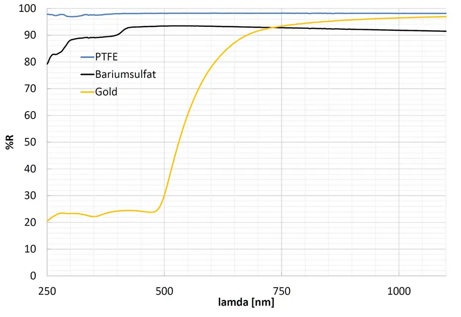
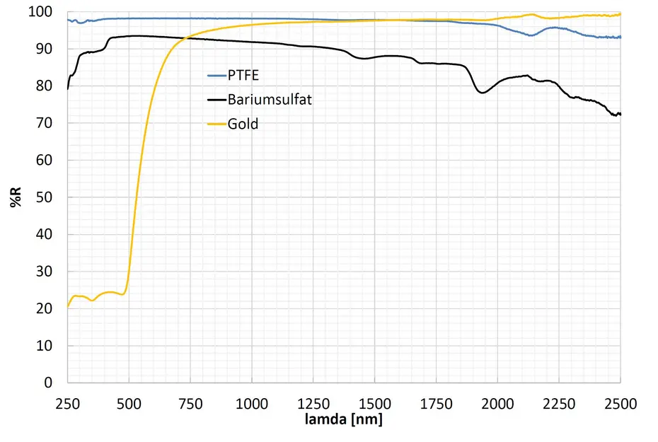
| Barium sulfate (BaSO₄) | 300–2400 nm | 88–93 % | Can be applied to very large spheres up to 2.5 m | Reflectance drops below 300 nm; sensitive to moisture |
| PTFE | 200–2500 nm | up to 99 % | Highest reflectance, reaches down into the UV-C | As a solid material only practical for small and medium diameters |
| Gold, 20 µm | 0.7–20 µm | 96–98 % | The only route into NIR and IR | Of no use in the visible or the UV |
The choice therefore follows the wavelength, not the price. Anyone measuring in the UV-C at 254 nm has no choice with barium sulfate – there PTFE is the only coating with a usable reflectance. Anyone needing a two-metre sphere for luminous flux measurements has no choice either, the other way round: solid PTFE cannot be built at that size.
Design: diameter, port fraction and baffle
Three quantities are linked, and none can be fixed on its own.
The port fraction f. Every opening is a spot without reflection and acts like a black patch. As a rule of thumb all openings together should stay below 5 % of the inner sphere surface; for accurate luminous flux measurements well below that. The formula above gives the reason: f enters the sphere multiplier directly.
The diameter. It follows the device under test. For the sphere to integrate the flux rather than image the source, the test object has to be small against the sphere – as a rule of thumb at most one tenth of the sphere diameter. A 30 cm LED luminaire therefore needs a sphere of around three metres, while a single 5 mm LED manages with 50 mm. The second link is the port fraction: a larger sphere tolerates a smaller fraction at the same port diameter.
The baffle. A small screen between source and detector. Without it, light falls directly from the source onto the detector and the measurement depends on the radiation direction again – exactly what the sphere is there to prevent.
Self-absorption. The test object itself swallows light: a lamp with a large base takes more from the sphere than a small LED. This is corrected with an auxiliary lamp, measured once with and once without the test object. For accurate luminous flux measurements it is not an accessory but a prerequisite.
Measuring laser power and laser energy in an integrating sphere
A laser beam brings three properties that distort any direct measurement: a beam profile unevenly distributed across the detector area, an angle of incidence the responsivity reacts to, and a polarisation. The integrating sphere removes all three: after the first diffuse reflection the light is unpolarised, without direction and evenly spread across the wall. The detector sees nothing but an irradiance.
The second reason is power density. A 10 W beam of 1 mm diameter carries roughly 1.3 kW/cm² – enough to destroy any semiconductor detector instantly. The sphere spreads the same power over its entire inner surface; at 100 mm diameter that is 314 cm². What reaches the detector is thus more than three orders of magnitude lower.
Pulsed lasers are integrated over the pulse: what is measured is energy in joules rather than power in watts. The sphere changes nothing about that – here too it delivers the advantage that beam profile and alignment do not matter.
Two points remain. First, the reflectance at the laser wavelength has to be known – a sphere calibrated at 550 nm measures wrongly at 1064 nm. Second, the coating is thermally limited: at continuous-wave powers in the hundreds of watts, thermal design belongs in the conversation.
Technical data for BaSO4, gold or PTFE integrating spheres
| Diameter | see: part numbers |
| customer-specific on request | |
| Coating | Barium sulfate (BaSO₄) |
| PTFE | |
| Gold, 20 µm | |
| Ports | 2 (standard) |
| Baffles | 1 (standard) |
| Options | internal illumination |
| additional ports | |
| Accessories | Light traps |
| Radiometer | |
| Spectrometer | |
| Port plug | |
| Port reducer |
Order numbers, scope of delivery, accessories and versions
| Coating | Wavelength range |
|---|---|
| Barium sulfate (BaSO₄) | 300–2400 nm |
| PTFE | 200–2500 nm |
| Gold | 0.7–20 µm |
The coating determines the usable wavelength range. Barium sulfate is the standard coating, PTFE reaches further into the UV and the near infrared, gold is the choice for the mid infrared.
| Inner diameter | Available with |
|---|---|
| 25 mm | PTFE |
| 50 mm | PTFE, gold |
| 75 mm | PTFE, gold |
| 100 mm | PTFE, gold |
| 150 mm | barium sulfate, PTFE, gold |
| 200 mm | barium sulfate, gold |
| 300 mm | barium sulfate, gold |
| 500 mm | barium sulfate, gold |
| 600 mm | barium sulfate, gold |
| 800 mm | barium sulfate |
| 1000 mm | barium sulfate, gold |
| 1650 mm | barium sulfate |
| 2500 mm | barium sulfate |
Other diameters are made to order. Also possible: additional inputs and outputs beyond the standard of two, auxiliary illumination and hinged hemispheres. Available as accessories: light traps, radiometers, spectrometers, port baffles and port adapters.
| Inner diameter | Barium sulfate | PTFE | Gold |
|---|---|---|---|
| 25 mm | – | 850301 | – |
| 50 mm | – | 850302 | 850502 |
| 75 mm | – | 850303 | 850503 |
| 100 mm | – | 850304 | 850504 |
| 150 mm | 850106 | 850306 | 850506 |
| 200 mm | 850108 | – | 850508 |
| 300 mm | 850112 | – | 850512 |
| 500 mm | 850130 | – | 850513 |
| 600 mm | 850135 | – | 850514 |
| 800 mm | 850138 | – | – |
| 1000 mm | 850140 | – | 850516 |
| 1650 mm | 850165 | – | – |
| 2500 mm | on request | – | – |
The 2500 mm sphere is made on request; in 2003 we delivered one to the PTB in Braunschweig.
Integrating sphere - image source
This website used images with permission of the PTB, the German national test authority, located in Braunschweig. More information can be found on PTB website or in publication „Messung von Licht. Photometrie (German)“.
Work in which measurements were made with integrating spheres from Opsytec:
- Luminescence and Photochromism in Lanthanide‐Doped Hackmanites — Baggott, J.; Tuomisto, M.; Williams, J. A. G. et al. · Advanced Optical Materials · 2026
- Customizing Tactile and Visual Perceptions of Organic Light–Emitting Diodes by Surface Coatings — Buhl, J.; Cojocaru, A.; Gerken, M. · Advanced Intelligent Systems · 2021
- Design of Instrumentation & Control and Optical Table Instruments for the Divertor Flow Monitor Diagnostic at ITER
The details come from Crossref. Authorship and content rest with the respective research groups.
These are the rules most often consulted in practice for integrating spheres — from measurement through limits to the requirements on the device:
- DIN EN ISO/IEC 17025:2018-03 — General requirements for the competence of testing and calibration laboratories
- CIE 250:2022 — Spectroradiometric Measurement of Optical Radiation Sources
- ISO/CIE 19476:2014 — Characterization of the performance of illuminance meters and luminance meters
All rules for integrating spheres are listed in the standards finder.
Not a normative reference. What counts is always the currently valid edition in the original text.