Air-cooled UV-LED series L
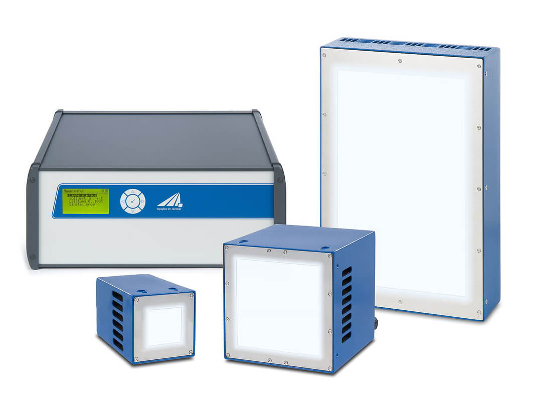
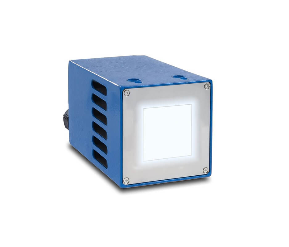
The UV LED series L is an air-cooled UV LED floodlight system for industrial irradiation. It reaches up to 6.0 W/cm² on the irradiated surface in the wavelengths 365, 385, 395, 405 and 450 nm. Five light-emitting areas from 30 × 30 mm to 200 × 100 mm cover electrical ratings from 50 W to 1000 W; a fan on the rear side dissipates the waste heat, so no chiller or water connection is needed.
This combines the benefits of UV LEDs over UV lamps – instant start, dimmability, long service life and lower heat input – with an economical UV LED system. The high irradiance enables short processing times, and the wavelength can be matched to the requirements of the photoinitiator. Customized UV LED modules are available on request.
The generously dimensioned cooling surface minimizes noise emission and thermal drift.
Because of the modular construction it is possible to connect different UV LED heads to the control unit LedControl S.
You will benefit from the modular and exchangeable UV LED series. By means of the intelligent control unit, you can set the power to between 2% and 100%. Short clock cycles with the highest precision are possible due to the trigger input and the internal timer.
To control the UV-LED L series, we offer the LedControl S as a desktop device and the LedControl DC for top-hat rail mounting. Our UV floodlights are supplied with suitable interfaces.
The LedControl S can be configured as a master or slave and can be cascaded as required. With the LedControl 5S, up to 5 UV LEDs can be controlled individually. It is controlled via RS485, USB or RS232, which facilitates industrial use. Optional digital and analog PLC inputs are also available.
The LedControl DC is ideal for integration into PLC systems and achieves a high level of performance.
Furthermore, the control unit features internal fault detection and thus ensures the utilization in the industrial production. For the monitoring of UV LEDs we recommend our calibrated UVA+- sensors. These are available as PLC sensors and hand radiometers.
Applications of air-cooled UV-LED series L
- Industrial UV curing and bonding
- IC Encapsulation
- UV sealing
- Hairline / leak detection using fluorescence markers
- Fluorescence Spectroscopy
- Surface Inspection
How a UV bonding or potting process with area modules is designed and released for production is described on the page UV bonding, potting and encapsulation.
3D Calculation Tool for Custom Designs
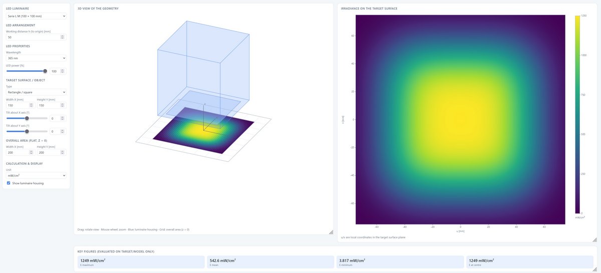
Calculate the irradiance on the component – also with STEP data, free of charge in the browser.
Calculate Series L arrays in 3D
How many Series L modules are needed to illuminate a component surface evenly can be determined in advance with the UV-LED 3D Irradiance Calculator. Emitting areas from 30 × 30 to 200 × 100 mm can be combined into arrays; the calculator provides irradiance, uniformity and cross-sectional profiles – including on imported STEP or STL geometries.
Common technical data UV-LED series L
| Wavelength | 365, 385, 395, 405, 450 nm |
| Emission, peak tolerance | ± 5 nm |
| Emission, FWHM | 10–20 nm |
| Uniformity | > 90 %, centric, 10 mm distance, dropping towards the edge (see fig.) |
| Cooling | air-cooling |
| Connections | trigger in, interlock in, optional dimming in (0–10 V), failure out |
| Programming, optional | RS485, RS232 or USB |
| Internal security circuit | Over-temperature, LED defect |
| Mains | 100–240 V, 50/60 Hz |
| Cable length | 3 m, up to 10 m (opt.) |
| Classification | risk group 3 according to DIN EN 62471:2009-03 |
| Operating temperature | 5 to 40 °C |
| Storage temperature | -10 to 60 °C |
| Humidity | below 80 %, non-condensing |
| Version | XS-HO / XS, S, M, L |
| Irradiance 365 nm | 4500 / 1250 mW/cm² |
| Irradiance 385 nm | 6000 / 1600 mW/cm² |
| Irradiance 395 nm | 5800 / 1600 mW/cm² |
| Irradiance 405 nm | 5800 / 1600 mW/cm² |
| Irradiance 450 nm | 6000 / 2200 mW/cm² |
| Emitting area | 30 × 30 mm |
| Dimensions | 70 × 70 × 85 mm |
| Power (el.) | 50 W |
| Emitting area | 100 × 10 mm |
| Dimensions | 135 × 135 × 145 mm |
| Power (el.) | 200 W |
| Emitting area | 100 × 50 mm |
| Dimensions | 135 × 135 × 145 mm |
| Power (el.) | 250 W |
| Emitting area | 100 × 100 mm |
| Dimensions | 135 × 135 × 145 mm |
| Power (el.) | 500 W |
| Emitting area | 200 × 100 mm |
| Dimensions | 267 × 135 × 145 mm |
| Power (el.) | 1000 W |
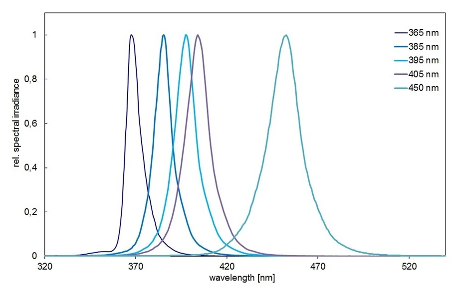
Spectra of the UV-LED series L
The air-cooled series L covers the same five wavelengths as the water-cooled series SFL. Across the dimming range from 2 to 100 % the peak wavelength stays inside the production tolerance of ± 5 nm – a dimmed module therefore does not shift its spectrum noticeably, unlike a discharge lamp run at reduced power. Two wavelengths result from two modules on a shared controller.
Irradiance, uniformity and spectra
The irradiance decreases with the distance. Measured centrally below the UV-LED module XS-HO at 385 nm and 100 % power, referred to the lower edge of the module:
| Distance | Irradiance |
|---|---|
| 5 mm | 6.2 W/cm² |
| 10 mm | 6.0 W/cm² |
| 15 mm | 5.8 W/cm² |
| 20 mm | 5.6 W/cm² |
| 30 mm | 5.4 W/cm² |
The values of the other sizes and wavelengths are listed in the table "Irradiances of UV-LED spot lamps" further down this page.
The common technical data give a uniformity of more than 90 %, measured centrally at a distance of 10 mm and dropping towards the edge. The two diagrams show the profile along the Y axis; the emitting area is shaded grey.
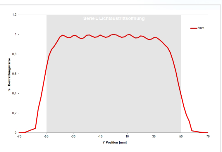
At a distance of 5 mm the irradiance stays above 90 % of the maximum across the emitting area and only drops at its edge. The greater the distance, the flatter and wider the profile and the lower the irradiance - about 0.8 of the maximum at 10 mm and about 0.5 at 20 mm:
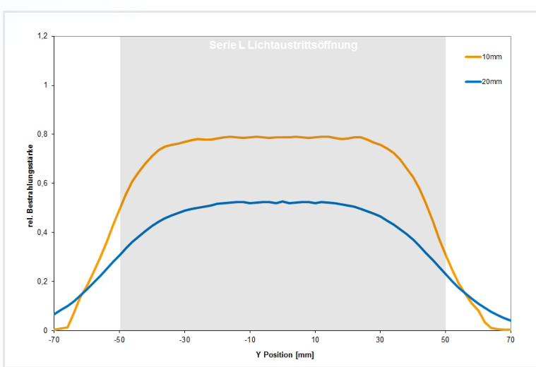
These are orientation values: they depend on the size, the wavelength and the distance.
Besides the UV-A and the blue wavelengths we manufacture customized UVB and UVC LED modules. Between 265 nm and 285 nm they reach an irradiance of 100 mW/cm². Available peak wavelengths:
| Peak wavelength |
|---|
| 265 nm |
| 272 nm |
| 275 nm |
| 280 nm |
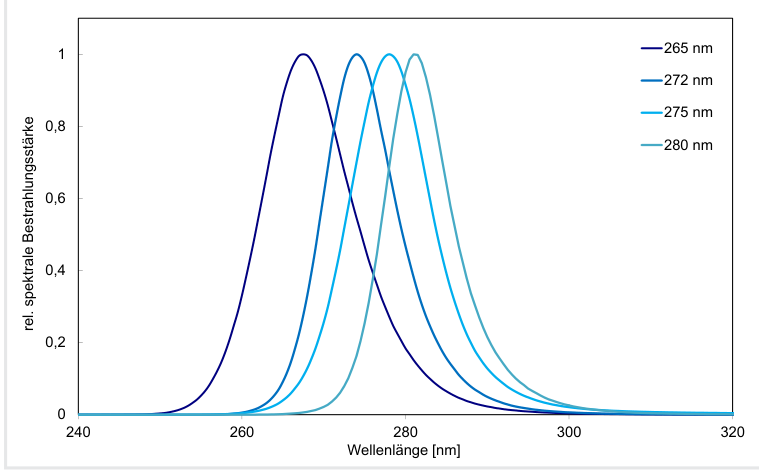
Please ask us for the wavelength that suits your application.
Remote control of the LedControl
The LedControl can be controlled through the programming interface on the rear - USB, RS485 or RS232 as required. Communication uses ASCII, here with "switch on" as an example:
- the control sends:
LOnOff:1! - the LedControl answers:
LOnOff: 1 (CRC-16)
Every channel can be controlled individually. The LedControl only sends when the control asks for it, and any number of LedControl units can be cascaded.
Through the PLC interface option the LED power (0 to 10 V), switching on and off (trigger input 24 V) and the status (trigger output 24 V) are set and queried. With its robust signals this option suits simple integration into a plant.
Control uses short ASCII commands. A selection:
| Command | Meaning |
|---|---|
| LAnzahlCH? | query the connected channels |
| LSelect: 0 1 !? | set the active channels |
| LPowerSet: 000.0 033.7!? | set the power |
| LTriggerOnOff: 11!? | activate the trigger input |
| LFirmware? | query the firmware version |
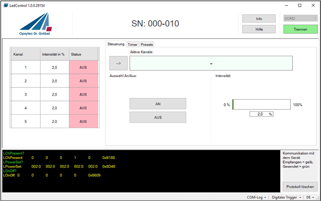
Remote software for testing the programming interface straight away is available. The test and control software shows the channels with intensity and status, switches them individually, sets timers and presets and logs the communication with the device.
The PLready safety option
To make machines safe and to meet the requirements of the machinery directive 2006/42/EC, safety functions are needed in the controls. Usually the required performance level PLr is determined for every safety function. This is where the first difficulty with UV installations begins: the severity of the injury, the frequency and duration of exposure and the avoidance of the UV hazard have to be determined.
In the short term, UV exposure of the skin leads to erythema, elastosis and skin cancer; exposure of the eye can lead to photokeratitis, conjunctivitis and cataractogenesis. Skin cancer is a severe and usually irreversible injury.
Directive 2006/25/EC on artificial optical radiation permits regular exposure up to a daily exposure limit of 30 J/m². The severity of the injury can therefore be reduced through the duration and the intensity of the exposure without having to achieve absolute zero exposure: if the limit is observed, healthy adults can be expected to be exposed repeatedly without acute harmful effects. In the event of a fault, a short exposure may cause a reversible injury such as a slight erythema. The boundary is not reliable, however, and measures and safety functions are needed in every case.
Measurements are possible on existing installations; during the planning phase they are not, or only with additional effort, which is why a higher PLr is often demanded. This is exactly what the LedControl and the PLready option are for - already at the planning stage.
The PLready safety option is suitable up to PL category 4 according to EN ISO 13849-1 and SIL 3 according to EN 62061, provided that cross-faults in the control of the LED module and in the sensor circuit can be excluded.
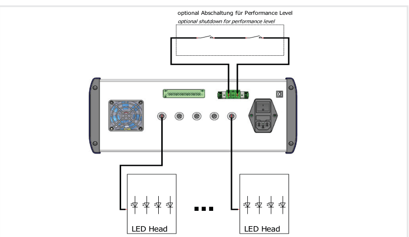
It works with a safety extra-low voltage (SELV) of 48 VDC that is safely separated by an external circuit and can switch the LED modules off completely in the event of a fault.
The optional shutdown for the performance level separates the LED modules through an external contact:
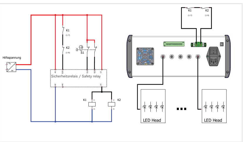
A two-channel safety door monitoring with automatic start is shown in the following example. Compared with simply separating the DC voltages, the advantage is the monitoring of the external contactors. The example is suitable up to category 4, PL e (EN ISO 13849-1) or SIL 3 (EN 62061), provided that cross-faults in the control of the actuator and in the sensor circuit can be excluded.
Safety instructions
The device emits UV-A and blue light. UV radiation is invisible. Any visible light is only luminescence excited by the radiation; it is usually much weaker than the exciting UV radiation. The irradiance of the device is several hundred times stronger than that of sunlight.
UV-A radiation can cause cataracts in the lens of the eye and inflammation of the retina. Always wear suitable UV protective goggles when operating the device. UV-A also causes skin discolouration and skin ageing; use suitable clothing, gloves and further personal protective equipment - depending on the irradiation dose.
The devices are designed and classified according to DIN EN 62471:2009-03 "Photobiological safety of lamps and lamp systems"; the series L falls into risk group 3. Do not look into the LED and do not expose the skin to the UV radiation permanently.
We are glad to support you in setting up UV workplaces and with the risk assessment according to DIN EN 14255:2005.
Order numbers, scope of delivery, accessories and versions
| Size | Order number |
|---|---|
| UV-LED L-XS-HO | 860615-LXSHA |
| UV-LED L-XS | 860615-LXS |
| UV-LED L-S | 860615-LS |
| UV-LED L-M | 860615-LM |
| UV-LED L-L | 860615-LL |
The sizes XS to L differ in the irradiated area; XS-HO is the high-output version of the smallest size.
Scope of delivery: the UV-LED module, the LEDControl, a connecting cable of 3 m, the manual and the options ordered. Please state the wavelength, the optic and the options with your order.
| Wavelength | Addition to the order number |
|---|---|
| 365 nm | -365 nm |
| 385 nm | -385 nm |
| 395 nm | -395 nm |
| 405 nm | -405 nm |
| 450 nm | -450 nm |
The order number is made up of the size and the wavelength - for the UV-LED L-XS-HO at 365 nm therefore 860615-LXSHA-365 nm. The peak wavelength lies within ± 5 nm.
| Version | Order number |
|---|---|
| LEDControl S | 860609B |
| LEDControl 5S-500W | 860610B5-500W |
| LEDControl DC | 860610DC |
The modules are operated through a LedControl - S for mains operation, 5S-500W for up to five modules, DC for operation at 24 V.
| Option | Order number |
|---|---|
| PLready safety option | 860609PL |
| Programming interface RS485 * | 860609-RS485 |
| Programming interface RS232 * | 860609-RS232 |
| Programming interface USB * | 860609-USB |
| Test and control software | 860609-SW |
| PLC interface option (I/O) | 860609-CP |
The interfaces and the PLready safety option are ordered together with the control unit.
* including the PLC interface option.
| Designation | Order number |
|---|---|
| Connecting cable UV-LED, 3 m | 860609C |
| UV protective goggles | 918800 |
| Foot switch | 860611 |
| Wall mount for the LEDControl | 860609-WA |
The UV protective goggles protect the eyes and the surroundings from stray radiation; the emitters are classified in risk group 3 according to DIN EN 62471.