Surface LED series SFL-UV
The UV LED floodlight SFL-UV is a water-cooled high-power source for large-area, uniform UV irradiation. Three light-emitting areas from 100 × 100 mm to 200 × 200 mm are available in the wavelengths 365, 385, 395, 405 and 450 nm; the HO version reaches up to 6000 mW/cm², the ECO version up to 2200 mW/cm², each measured at a distance of 10 mm from the emitting window.
For acceptance testing and routine checks of the irradiance we offer matching UV meters and radiometers.
The SFL-UV modules use an intelligent LED driver. The absence of ineffective infrared radiation reduces the heat compared to conventional UV lamps.
Customized sizes are available on request.
We offer the LedControl S as a desktop device and the LedControl DC for top-hat rail mounting to control the UV LED floodlights. The UV floodlights are supplied with the appropriate interfaces.
The LedControl S can be configured as a master or slave and can be cascaded as required. With the multi-channel LedControl 5S, up to 5 UV LEDs can be controlled individually. It is controlled via RS485, USB or RS232, which makes it easy to use in industrial production. Digital and analog PLC inputs are also available as an option.
The LedControl DC is ideal for integration into a PLC and achieves a high performance level.
A timer for the irradiation times between 0.01 s and 9999 s is already integrated. Optionally you can choose between continuous or triggered operation.
The large-area UV LED light source operates reliably with optional internal and external control. The optical feedback option allows for connecting an external sensor to the SF-UV-LED driver. The irradiance can be measured with our long-term stable UV sensors at the desired position. To monitor and control irradiance, the internal feedback diode can be calibrated to the external sensor. The internal feedback keeps the irradiance constant to minimize LED temperature drift and aging.
Applications of surface LED series SFL-UV
- Industrial UV curing and bonding
- IC Encapsulation
- UV sealing
- Hairline / leak detection using fluorescence markers
- Fluorescence Spectroscopy
- Surface Inspection
For continuous web and printing processes, the page UV measurement in industrial printing describes the measurement tasks at the workpiece plane.


3D Calculation Tool for Custom Designs
Calculate the irradiance on the component – also with STEP data, free of charge in the browser.
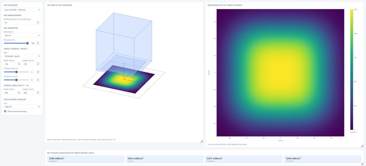
Design the irradiance of the SFL-UV in the 3D calculator
For the SFL-UV, the UV-LED 3D Irradiance Calculator shows how the irradiance develops beyond the nominal distance of 10 mm: emitting area, wavelength, power and working distance can be set, several emitters combined into an array, and the result evaluated on flat, inclined or STEP-imported components.
Common technical data UV-LED flood lamp SFL
| Wavelength | 365, 385, 395, 405 or 450 nm |
| Irradiance 365 nm | 4500 / 1250 mW/cm² |
| Irradiance 385 nm | 6000 / 1600 mW/cm² |
| Irradiance 395 nm | 5800 / 1600 mW/cm² |
| Irradiance 405 nm | 5800 / 1600 mW/cm² |
| Irradiance 450 nm | 6000 / 2200 mW/cm² |
| Emission, peak tolerance | ± 5 nm |
| Emission, FWHM | 10–20 nm |
| Uniformity | >90 %, typical at a distance of 10 mm (5 % std. dev.) |
| Cooling water temperature | min. 18 °C, non-condensing, max. 40 °C |
| Connections | trigger in, dimming in (0–10 V), interlock in, failure out |
| Programming, optional | RS485, RS232 or USB |
| Internal security circuit | Over-temperature, LED N.C. |
| Optical feedback, opt. | internal and external sensor |
| Cable length | 3 m, optionally up to 10 m |
| Water inlet, pressure | < 4 bar |
| Classification | risk group 3 according to DIN EN 62471:2009-03 |
| Operating temperature | 5 to 40 °C |
| Storage temperature | -10 to 60 °C |
| Humidity | below 80 %, non-condensing |
| Emitting area | 100 × 100 mm |
| Dimensions | 135 × 135 × 75 mm |
| Power HO version | 2000 W |
| Power ECO version | 500 W |
| Cooling water flow | 4 to 1 l/min (typical) |
| Emitting area | 200 × 100 mm |
| Dimensions | 235 × 135 × 75 mm |
| Power HO version | 3800 W |
| Power ECO version | 1000 W |
| Cooling water flow | 10 to 2.5 l/min (typical) |
| Emitting area | 200 × 200 mm |
| Dimensions | 235 × 235 × 75 mm |
| Power HO version | 7700 W |
| Power ECO version | 1900 W |
| Cooling water flow | 20 to 5 l/min (typical) |
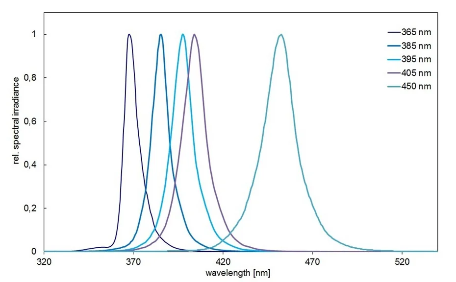
Spectra of the large-area UV-LED SFL
The SFL-UV comes in all five wavelengths, but the achievable irradiance depends on the choice: 4500 mW/cm² at 365 nm against 6000 mW/cm² at 385 and 450 nm in the HO version. The figure, by contrast, normalises every curve to its own maximum and therefore shows the spectral position alone. For arrays, modules of different wavelength can be placed side by side.
Uniformity of the irradiation
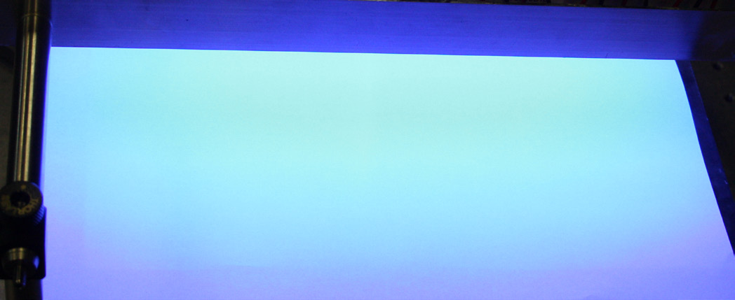
The common technical data give a uniformity of typically more than 90 % at a distance of 10 mm from the emitting window, with a standard deviation of 5 %. The area also stays uniformly irradiated at a greater distance - the photograph shows an SFL-UV-L ECO flood lamp with 385 nm UV LEDs.
These are orientation values: they depend on the emitting area, the wavelength, the power level and the distance. The greater the distance, the larger the irradiated area and the lower the irradiance.
Remote control of the LedControl
The LedControl can be controlled through the programming interface on the rear - USB, RS485 or RS232 as required. Communication uses ASCII, here with "switch on" as an example:
- the control sends:
LOnOff:1! - the LedControl answers:
LOnOff: 1 (CRC-16)
Every channel can be controlled individually. The LedControl only sends when the control asks for it, and any number of LedControl units can be cascaded.
Through the PLC interface option the LED power (0 to 10 V), switching on and off (trigger input 24 V) and the status (trigger output 24 V) are set and queried. With its robust signals this option suits simple integration into a plant.
Control uses short ASCII commands. A selection:
| Command | Meaning |
|---|---|
| LAnzahlCH? | query the connected channels |
| LSelect: 0 1 !? | set the active channels |
| LPowerSet: 000.0 033.7!? | set the power |
| LTriggerOnOff: 11!? | activate the trigger input |
| LFirmware? | query the firmware version |
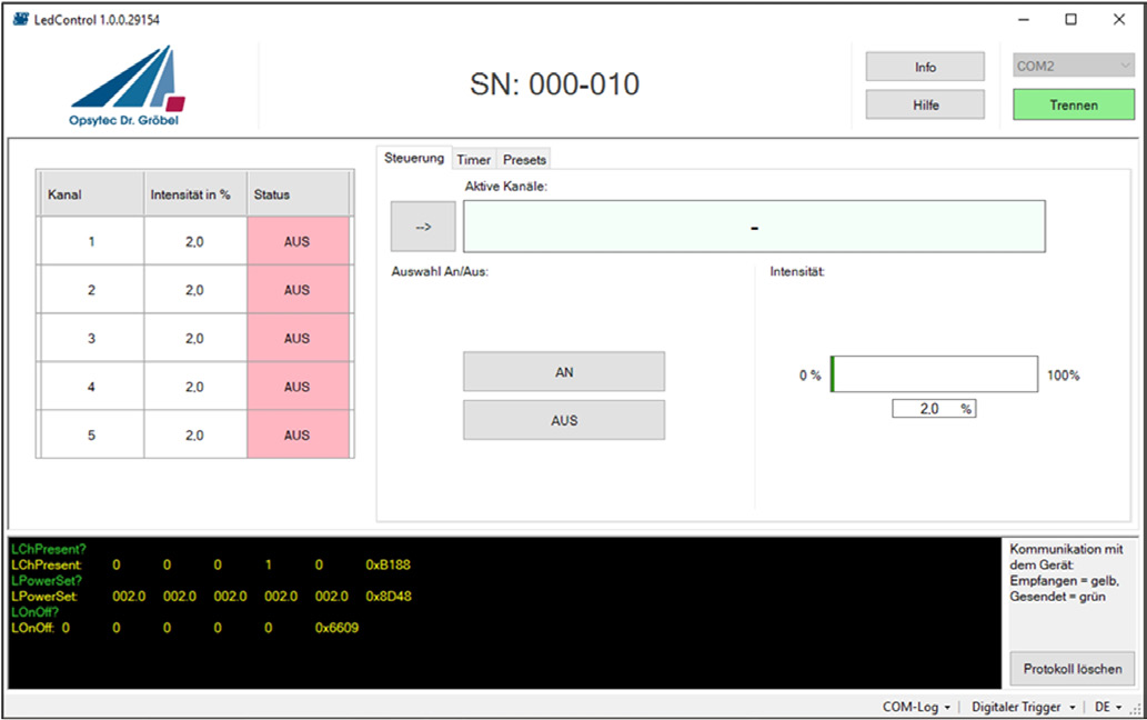
If the emitter is supplied with a programming interface, remote example software for testing straight away is included. The test and control software shows the channels with intensity and status, switches them individually, sets timers and presets and logs the communication with the device.
The PLready safety option
To make machines safe and to meet the requirements of the machinery directive 2006/42/EC, safety functions are needed in the controls. Usually the required performance level PLr is determined for every safety function. This is where the first difficulty with UV installations begins: the severity of the injury, the frequency and duration of exposure and the avoidance of the UV hazard have to be determined.
In the short term, UV exposure of the skin leads to erythema, elastosis and skin cancer; exposure of the eye can lead to photokeratitis, conjunctivitis and cataractogenesis. Skin cancer is a severe and usually irreversible injury.
Directive 2006/25/EC on artificial optical radiation permits regular exposure up to a daily exposure limit of 30 J/m². The severity of the injury can therefore be reduced through the duration and the intensity of the exposure without having to achieve absolute zero exposure: if the limit is observed, healthy adults can be expected to be exposed repeatedly without acute harmful effects. In the event of a fault, a short exposure may cause a reversible injury such as a slight erythema. The boundary is not reliable, however, and measures and safety functions are needed in every case.
Measurements are possible on existing installations; during the planning phase they are not, or only with additional effort, which is why a higher PLr is often demanded. This is exactly what the LedControl and the PLready option are for - already at the planning stage.
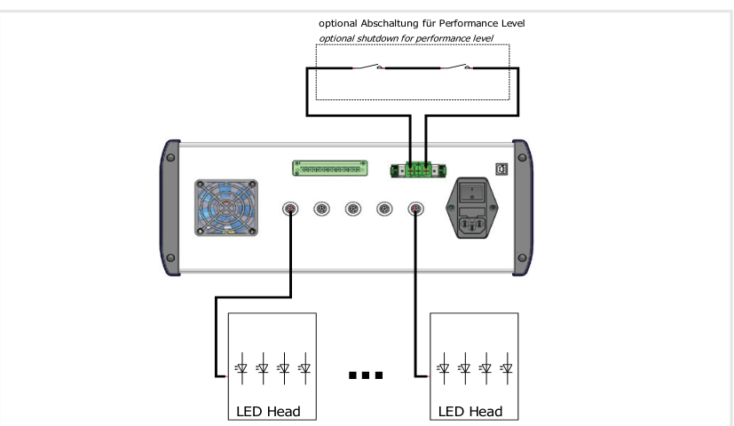
The PLready safety option is suitable up to PL category 4 according to EN ISO 13849-1 and SIL 3 according to EN 62061, provided that cross-faults in the control of the LED module and in the sensor circuit can be excluded.
It works with a safety extra-low voltage (SELV) of 48 VDC that is safely separated by an external circuit and can switch the LED modules off completely in the event of a fault.
The optional shutdown for the performance level separates the LED modules through an external contact:
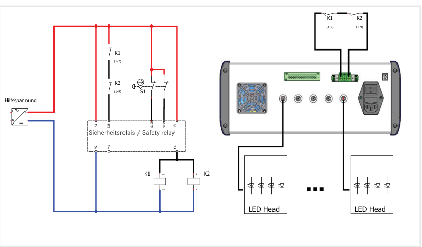
A two-channel safety door monitoring with automatic start is shown in the following example. Compared with simply separating the DC voltages, the advantage is the monitoring of the external contactors. The example is suitable up to category 4, PL e (EN ISO 13849-1) or SIL 3 (EN 62061), provided that cross-faults in the control of the actuator and in the sensor circuit can be excluded.
Safety instructions
The device emits UV-A and blue light. UV radiation is invisible. Any visible light is only luminescence excited by the radiation; it is usually much weaker than the exciting UV radiation. The irradiance of the device is several hundred times stronger than that of sunlight.
UV-A radiation can cause cataracts in the lens of the eye and inflammation of the retina. Always wear suitable UV protective goggles when operating the device. UV-A also causes skin discolouration and skin ageing; use suitable clothing, gloves and further personal protective equipment - depending on the irradiation dose.
The devices are designed and classified according to DIN EN 62471:2009-03 "Photobiological safety of lamps and lamp systems"; the SFL falls into risk group 3. Do not look into the LED and do not expose the skin to the UV radiation permanently.
We are glad to support you in setting up UV workplaces and with the risk assessment according to DIN EN 14255:2005.
Order numbers, scope of delivery, accessories and versions
| Version | Order number |
|---|---|
| SFL-UV-M ECO | 860616-M |
| SFL-UV-L ECO | 860616-L |
| SFL-UV-XL ECO | 860616-XL |
The sizes M, L and XL differ in the irradiated area.
Scope of delivery: the SFL-UV module, the LedControl, a cable of 3 m and the manual; when the optical feedback option is ordered, also a UV sensor with a factory calibration certificate. Please state the wavelength and the options with your order.
| Wavelength | Addition to the order number |
|---|---|
| 365 nm | -365 nm |
| 385 nm | -385 nm |
| 395 nm | -395 nm |
| 405 nm | -405 nm |
| 450 nm | -450 nm |
The order number is made up of the version and the wavelength - for the SFL-UV-M ECO at 365 nm therefore 860616-M-365 nm. The peak wavelength lies within ± 5 nm.
| Designation | Order number |
|---|---|
| Power level HO | 560609-HO |
The HO version (high output) delivers the higher irradiance.
| Version | Order number |
|---|---|
| LEDControl S | 860609B |
| LEDControl DC | 860610DC |
The emitters are operated through a LedControl - S for mains operation, DC for operation at 24 V.
| Option | Order number |
|---|---|
| Test and control software | 860609-SW |
| Programming interface RS485 * | 860609-RS485 |
| Programming interface RS232 * | 860609-RS232 |
| Programming interface USB * | 860609-USB |
| PLC interface option (I/O) | 860609-CP |
| PLready safety option | 860609PL |
The interfaces and the PLready safety option are ordered together with the control unit.
* including the PLC interface option.
| Designation | Order number |
|---|---|
| Wall mount for the LEDControl S | 860609-WA |
| Foot switch | 860611 |
| Connecting cable UV-LED, 3 m | 860609C |
| UV protective goggles | 918800 |
| Cable, per further metre | 86060X-m |
| Radiometer RMD | 814401 |
| UVA+ sensor | 814447 |
The connecting cable is 3 m long, on request up to 10 m; further metres are charged individually.
The UV protective goggles protect the eyes and the surroundings from stray radiation; the emitters are classified in risk group 3 according to DIN EN 62471.
The irradiance can be measured with the RMD radiometer and the UVA+ sensor; the sensor is also used to calibrate the optical feedback.
Publications using Opsytec UV LED light sources
We do not keep a separate bibliography for this individual device – publications usually name the product family, not the model. Listed here are the 10 most recent works in which Opsytec UV LED light sources were used.
Downloads
Matching accessories
- LedControl S
- LedControl DC
- Radiometric sensors