For UV and visible light
UV sensors and VIS sensors for laboratory and process
UV sensors and VIS sensors capture irradiance or dose within defined spectral ranges. What governs the selection is the source, the wavelength range, the expected reading, the angular distribution, the mounting position and the electrical interface. This category sorts sensors for hand-held instruments, stationary process monitoring and customer-specific measuring tasks.
View sensors as a 3D model
Look at the sensor heads from every side, rotate and zoom – directly in your browser.
Explore UV Sensors Interactively in 3D
The 3D product viewer displays Opsytec products as true-to-life 3D models. For measuring devices, you can interact with the display—including navigating the menus. Rotate, zoom, and explore radiometers and sensors right in your browser—no installation required!

Sensor groups by type of use
| Type of use | Sensors | Clarify before selecting |
|---|---|---|
| Hand-held measurement | Radiometer measuring heads for RMD and RM-12 | Spectral range, measuring range and matching display unit |
| Process and inline measurement | Inline sensors, PLC sensors with 0–10 V or 4–20 mA, PLC.D digital, PLC.net over Ethernet | Mounting position, interface and immunity to interference |
| Points that are hard to reach | UV probes, 6 mm outer diameter, up to 200 °C | Probe length, version (side-on, head-on, integrating) and aperture size |
| Wet installations and water disinfection | UVC-SE for UVC, UVx-SE in seven spectral ranges, both up to 10 bar | Pressure, mounting geometry and sealing faces |
| Visible range | VISB for 400–480 nm, LUX with V(λ) weighting | Required weighting function |
| Customer-specific | Custom builds, IP65, special housings, extended measuring and spectral ranges | Requirement, test scope and acceptance |
Which sensor do I need?
The selection follows two quantities. The spectral range follows the application – in curing processes, the absorption band of the photoinitiator. The measuring range follows the irradiance to be expected, not the instrument. The full selection sequence, with guide values per source, is set out under selecting a UV sensor.
The sensor has to match the spectrum, not just the spectral range. For low-pressure lamps a narrow-band weighting around 254 nm is sufficient, because practically all the UVC output sits in that line. Medium-pressure lamps emit broadband across the whole UVC range and require a sensor with a broad, flat UVC weighting calibrated for exactly that lamp type. UVC LEDs – typically 265 to 280 nm – require calibration to their peak wavelength. Without source-specific calibration factors, the same sensor does not deliver comparable values at all three sources. Why that is so is explained under design and error sources of UV sensors.
All sensors ship calibrated with a factory calibration certificate and can be recalibrated at any time; procedures and records are described under UV calibration. For continuous monitoring, inline sensors are available; workplace exposure measurements carry their own requirements for sensitivity and weighting – see workplace exposure measurement. Matching display units are listed under UV meters and radiometers, the interchangeable measuring heads under radiometer sensors and measuring heads. Repair and spare parts are handled under service and repair.
Radiometer sensors
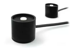
Interchangeable UV and light sensors Ø 40 mm in seven spectral ranges for RMD Pro, RMD Touch and RM-12.
UV curing sensors XT

Sensors with rod or light guide for irradiances up to 20 W/cm² (optionally 50 W/cm²) and temperatures up to 150 °C.
Inline sensors

Flat inline sensors, 15 mm high, for continuous monitoring of irradiance in UV systems.
PLC.net – Ethernet UV sensor

UV sensor with Ethernet and PoE; readings available via Modbus TCP and HTTP/JSON directly on the network.
PLC.D – digital UV sensors
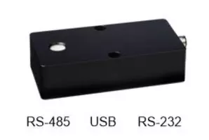
Digital UV and light sensors with RS-485, RS-232 or USB for direct connection to the PLC.
PLC sensors with analog output signals
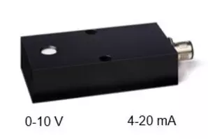
UV and light sensors with 4–20 mA, 0–10 V or 0–2 V output for direct connection to PLC controllers.
UV Probes

Compact UV probes, 15 or 30 cm long, for measurements at hard-to-reach locations up to 200 °C.
DVGW reference radiometer

Reference radiometer for monitoring UV drinking-water disinfection according to DIN 19294-3 (low pressure) and DIN 19294-4 (medium pressure).
Custom-made sensors

Examples of customer-specific adaptations of standard sensors: housing, spectral range and connection.
UVx-SE

Watertight sensor up to 10 bar for medium-pressure lamps and CIP environments in seven spectral ranges.
UVC-SE
Pressure-watertight UVC sensor up to 10 bar with integrated amplifier for low-pressure lamps in water disinfection.
UV sensing: what has to fit together
A UV sensor on its own is not yet a measurement. What finally produces a reliable value is a chain: sensor, spectral weighting, amplifier and interface, calibration, mounting position. Any link can shift the result by more than the resolution of the instrument; that is why it pays to design the sensing as a whole.
Besides spectral range and measuring range, two further decisions carry the design:
- Interface. 0–10 V or 4–20 mA for the plant, RS-485 or Ethernet where calibration status and sensor type should travel with the reading – this choice later decides whether a deviation is read as sensor drift or as a process fault.
- Mounting position. The sensor measures what arrives at the sensor, not what arrives at the workpiece. Distance, acceptance angle and window fouling decide whether the two are related.
Monitoring irradiance continuously in a plant calls for different properties than an acceptance measurement: the reading does not have to be most accurate on day one, it has to stay stable for years. How a UV sensor works internally and where its error sources lie is set out under how UV sensors work; the UV sensor finder locates the right sensor by spectral range and measuring task.
Applications of UV sensors and daylight sensors
- Dose control in UV curing and bonding
- Monitoring of UV irradiation
- Control of disinfection systems in the packaging industry
- UVC water disinfection, UVC wastewater treatment
- Lamp monitoring and quality assurance in lamp production
- Measurement of workplace safety due to artificial optical radiation
- Photometric measurements
- PLC-control and lamp power regulation
Find the right sensor
Find the right sensor: The UV Sensor Finder proposes the three best-matching UV sensors and meters by application, wavelength and form factor – with key values, system partner and reasons.