UVx-SE – waterproof UV sensor up to 10 bar, CIP-capable
The water-proof sensor UVx-SE serves as a robust, long-term stable measuring head for the precise measurement of UV irradiances in production lines that require wet cleaning. The sensors are calibrated with traceability to the PTB (Physikalisch Technische Bundesanstalt, the German national test authority) and can be exposed to a pressure of up to 10 bar. Seven spectral ranges and two measuring ranges up to 0–200 mW/cm² are available; at 24 V supply voltage the sensor delivers either 0–10 V or 4–20 mA.
The integrated electronics produce a signal that is transmitted to the PLC or panel meter, so that interference is minimized.
For small control tasks, the sensor UVx-SE can be connected to RM-32, which shows current irradiance on a 3.5-digit digital display and switches two relay contacts with adjustable warning and alarm signals.
Housing and window withstand cleaning agents, temperature changes and pressure – which makes the UVx-SE CIP-capable and able to stay in the plant during wet cleaning.
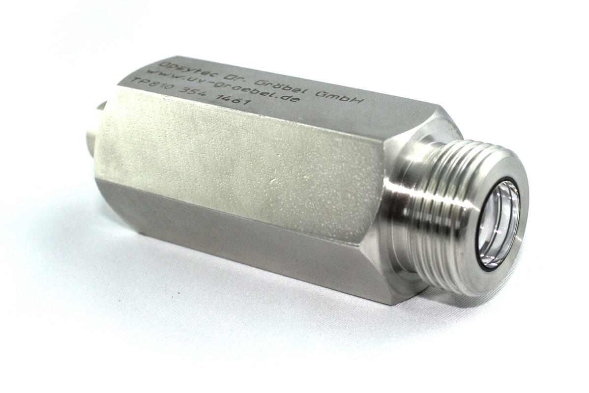


| Product type | UV sensor: Waterproof sensor for medium-pressure lamps and CIP environments in seven spectral ranges |
| Spectral range | UVC 200–280 nm, UVB 280–315 nm, UVA 315–400 nm, UVA+ 330–455 nm, UVBB 230–400 nm, VISB 400–480 nm, LUX 380–780 nm |
| Measuring range | 0–200 mW/cm²; 0–20 mW/cm² |
| Calibration uncertainty (typ.) | 4.5–6.0 % (k = 2) |
| Output / interface | Connection: G 3/4“; Output signal: 0–10 V or 4–20 mA |
| Time resolution | analogue sensor signal, determined by the instrument |
| Calibration | factory calibration, recalibratable |
| Standards / guidelines | no product-specific standard; calibration per DIN EN ISO/IEC 17025:2018 available |
| Suitable for | Water and environmental technology; UV disinfection; UV curing and photopolymerisation; Packaging and filling technology |
| Not suitable for | spectrally resolved measurement (peak wavelength, bandwidth); irradiance above 200 mW/cm² (standard range); sensor temperatures above 60 °C; dose measurement without instrument or controller |
| Datasheet revision | Rev. 2026-09-08 (e_water-proof-sensor-uvx-se.pdf) |
The calibration uncertainty stated above is the expanded uncertainty of the calibration (k = 2, confidence level approx. 95 %) and applies to the calibration source and the calibration conditions. In use the measurement uncertainty is larger: spectral mismatch at the source actually used, the sensor temperature, ageing since calibration as well as distance and alignment to the source are added to it. How these combine into an uncertainty budget is explained under Measurement uncertainty in UV measurement.
View the UVx-SE as a 3D model
Look at the pressure-resistant sensor from every side, rotate and zoom – directly in your browser.
The UVx-SE can be viewed from all sides in the 3D product viewer – true to the original, generated from the CAD design data. Because the UVx-SE sits at up to 10 bar in wet-cleaned lines, the sealing face, the window position and the connector version are the dimensions that matter when planning the installation.
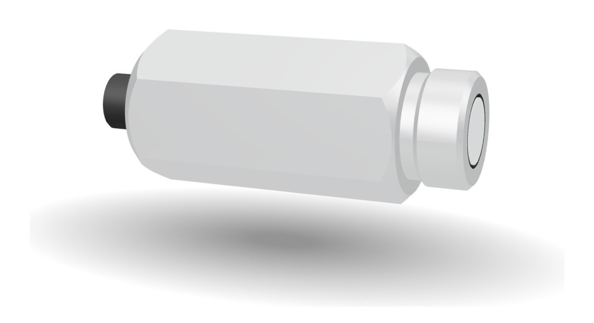
Technical data water proof UV-sensor UVx-SE
| Measuring range | 0–200 mW/cm² |
| Measuring range option | 0–20 mW/cm² |
| Connector | G 3/4“ |
| Dimensions | see drawing |
| Housing material | stainless steel |
| Weight | ~420 g |
| Water pressure | up to 10 bar |
| Operating voltage | 24 V |
| Operating current | <15 mA |
| Output | 0–10 V or 4–20 mA |
| Operating temperature | 0 to 60 °C |
| Storage temperature | -10 to 60 °C |
| Humidity | < 80%, non-condensing |
| Cable | 2 m – 10 m |
| Sensor connector | M12 (5-pole) |
Frequently asked questions: UVx-SE
The UVx-SE is the waterproof sensor for medium-pressure lamps and for systems where not only UVC is measured: it is available in the seven spectral ranges UVC, UVB, UVA, UVA+, UVBB, VISB and LUX. The UVC-SE, in contrast, is specialised for the 253.7 nm line of the low-pressure lamp. Both have a pressure-water-proof housing and an integrated amplifier with 4–20 mA or 0–10 V.
Standard is 0–200 mW/cm²; option 2 offers 0–20 mW/cm² for weak sources or large distances. The end value of the range corresponds to 20 mA or 10 V at the output. For medium-pressure lamps in water treatment systems the operating value at the sensor is typically in the range of some 10 mW/cm², so the standard range is sufficient; with measuring windows at large distance the sensitive option makes sense.
Yes, the housing is designed for wet cleaning and permanent contact with liquid; the stainless-steel housing is pressure-water-proof up to 10 bar, and the permissible operating temperature is 0 to 60 °C. Cleaning agents must not etch the quartz window; after aggressive media the transmission of the window should be checked. The PLC via 4–20 mA or the panel-mount RM-32 with alarm relays are suitable for the evaluation.
The calibration certificate states the expanded calibration uncertainty with k = 2; for the UVx-SE it is typically 4.5–6.0 %. In use the measurement uncertainty is larger, because spectral mismatch at the source actually used, sensor temperature, ageing and measuring geometry are added to it. How these combine into an uncertainty budget is explained under Measurement uncertainty in UV measurement.
Order numbers, scope of delivery, accessories and versions
| Output signal | Order number |
|---|---|
| UVx-SE, 0–10 V | 810382 |
| UVx-SE, 4–20 mA | 810383 |
Scope of delivery: the UVx-SE sensor, a protective cap and the factory calibration certificate. Please state the required spectral range and measuring range with your order.
| Length | Order number |
|---|---|
| Connecting cable, 2 m | 920310 |
| Connecting cable, 5 m | 920310-5 |
| Connecting cable, 10 m | 920310-10 |
| Length | Order number |
|---|---|
| Connecting cable, 2 m | 920310-I |
| Connecting cable, 5 m | 920310-I5 |
| Connecting cable, 10 m | 920310-I10 |
| Designation | Order number |
|---|---|
| Online monitor RM-32 | 670029 |
The UVx-SE can be operated on the panel meter RM-32: it shows the irradiance on a 3½-digit digital display and outputs warning and alarm signals through two relay contacts.
Connection and pin assignment
| Name | Wire colour | Connector PIN |
|---|---|---|
| GND / Shield | brown | PIN 1 |
| Supply 24 VDC | white | PIN 2 |
| not used | – | PIN 3 |
| Signal High 0 – 10 VDC | black | PIN 4 |
| Signal Low | grey | PIN 5 |
On versions with an open cable end there is no connector; the wire colours remain the same.
| Name | Wire colour | Connector PIN |
|---|---|---|
| Supply 24 VDC | brown | PIN 1 |
| Supply 24 VDC | white | PIN 2 |
| GND / Shield | blue | PIN 3 |
| GND / Shield | black | PIN 4 |
| not used | – | PIN 5 |
The sensor sits in the current loop: PIN 1 and PIN 2 carry the supply, PIN 3 and PIN 4 the return. The measuring instrument or PLC input is placed in the return line and reads the loop current. On versions with an open cable end there is no connector; the wire colours remain the same.
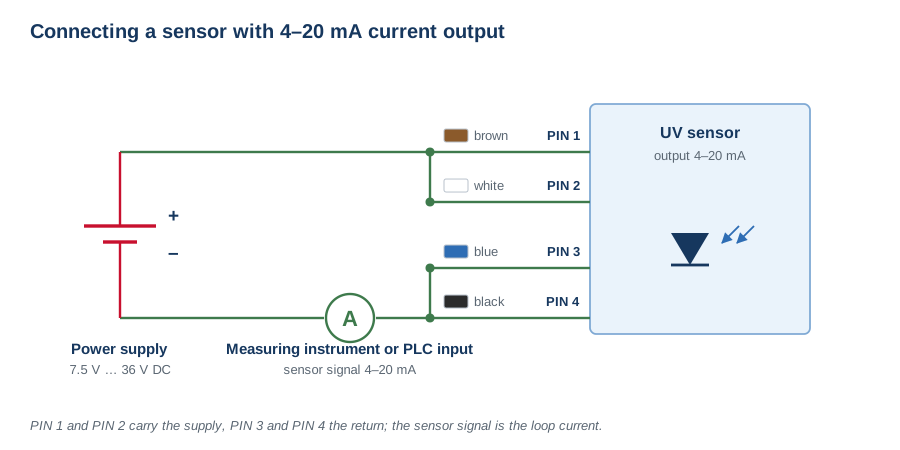
Connection in the current loop, supply 7.5 V to 36 V DC.
The connecting cables are available with an M12 female or an M12 male connector. Both diagrams show the mating face, so the contacts are mirrored with respect to each other. The keyway fixes the orientation.

M12 female connector, 5-pole – view onto the mating face.
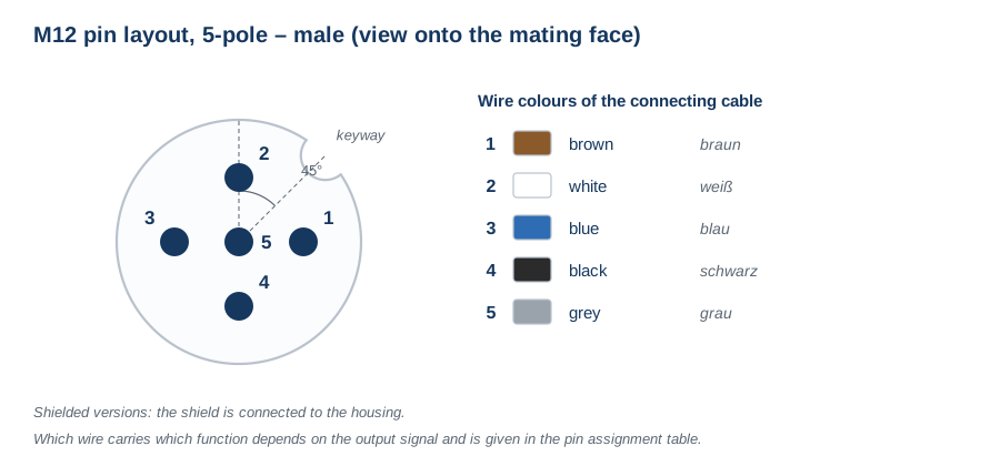
M12 male connector, 5-pole – view onto the mating face.