UV Technology for Aerospace Applications
In aerospace, ultraviolet radiation performs three technically distinct functions: as an excitation source for fluorescent crack detection on safety-critical components, as a photochemical tool for contactless surface cleaning of optical and sensor assemblies, and as a defined stress parameter in accelerated material aging. All three applications combine a high standard of proof with small but safety-critical batch sizes – an overlooked defect has a greater impact here than in many other industries. Key physical quantities are the irradiance at the actual part location (in µW/cm² or W/m²), the spectral distribution of the source, the exposure time or dose and – for material testing – the question of which part of the real space environment a test chamber actually reproduces. The technical challenge is to capture these quantities where the process actually takes place, not where the measurement is easiest.

How is UV technology in aerospace developing?
The underlying demand driver is fleet growth itself: in its Commercial Market Outlook 2026, Boeing forecasts worldwide demand for around 43,625 new commercial aircraft between 2026 and 2045, with the global fleet growing by almost 80 percent to more than 50,000 aircraft (Boeing Commercial Market Outlook, 2026). Over its service life, each of these aircraft undergoes recurring, normatively mandated NDT cycles on highly stressed components such as turbine blades, landing gear and structural fittings. Technically, fleet growth therefore means not only more inspection volume but also increasing pressure on the process reliability of the inspection itself: as the number of inspection cycles grows, so does the number of occasions on which a non-compliant irradiance goes undetected. At the same time, environmental regulations are tightening requirements on inspection materials – the market is shifting toward water-washable, lower-solvent penetrants and closed rinse systems, which in turn requires closer process monitoring of the optical excitation, since the chemical composition and fluorescence behavior of the inspection materials are being held to tighter tolerances (Strategic Market Research, FPI Market, 2024).
The shift from mercury-vapor UV-A lamps to UV-A LED sources under ASTM E3022 eliminates the warm-up drift of classic Hg lamps, but at the same time changes the excitation spectrum: the LED's narrower spectral distribution must be re-evaluated against the absorption characteristics of the fluorescent dyes used, since a numerically equal irradiance under a different spectrum does not automatically deliver the same excitation efficiency. In photochemical cleaning, the technology base is shifting toward mercury-free xenon excimer sources, easing regulatory pressure on mercury-containing light sources without reducing photochemical effectiveness. At the same time, the regulatory trend toward water-washable, lower-solvent penetrant systems with closed rinse loops is further raising the requirements for a constant, well-documented optical excitation, as inspection material manufacturers specify tighter fluorescence specifications. In automation, inline sensor integration in robotic inspection cells continues to spread, aiming to document every individual inspection run metrologically instead of only calibrating the system as a whole periodically. In space material testing, the importance of combined multi-stress test rigs that bring together UV irradiation, thermal vacuum and particle radiation in a single facility is growing, because individual test rigs cannot reproduce the interaction between stress types – such as the UV degradation accelerated by atomic oxygen.
Market sizes, growth rates and sources for this application field are summarised on the page Market development of UV technology.
How does fluorescent penetrant inspection work?
Fluorescent Penetrant Inspection (FPI) uses capillary forces to draw a low-viscosity, dye-loaded penetrant into surface-breaking discontinuities – cracks, porosity, lack of fusion – on a non-porous part. After a defined dwell time, excess penetrant is removed from the surface, a developer is applied, and the penetrant remaining in the discontinuity is drawn back to the surface by capillary action. The fluorescent dye in the penetrant absorbs UV-A radiation (typical excitation maxima lie in the 350–380 nm range) and re-emits part of the absorbed energy as visible light at a longer wavelength – a red-shift known as the Stokes shift. Because the emission is spectrally separated from the exciting radiation and the inspection booth is darkened with limited residual light, even a tiny, sub-visual defect appears as a clearly visible, yellowish-green indication against a dark background. Detection sensitivity depends not on the penetrant alone, but equally on the excitation: wavelength, irradiance at the part, uniformity of the illumination field and residual ambient light together determine whether an indication is actually detected.
Which technologies are used?
The three roles described – crack detection, photochemical cleaning, material aging – each rely on different light sources with their own normative framework.
| Technology | Characteristics | Advantages | Limits | Typical application |
|---|---|---|---|---|
| Mercury-vapor UV-A lamp | Line spectrum around 365 nm, standardized per ASTM E2297 | High achievable irradiance, established inspection practice | Warm-up time to stable output, mercury content, bulb aging | Stationary FPI inspection stations |
| UV-A LED lamp | Narrowband emission, individually and type-certified per ASTM E3022 | Instant stability with no warm-up phase, no mercury issue, long service life | Aging-related lumen decline over service life must be verified | Portable hand-held lamps, field MRO use |
| Low-pressure Hg lamp (UVC/ozone) | Dual line at 185 nm and 254 nm | Generates ozone and reactive oxygen in a single step, low-cost | Contains mercury, limited penetration depth of effect | Photochemical cleaning of optical assemblies |
| Xenon excimer lamp (VUV, 172 nm) | Quasi-monochromatic VUV emission, mercury-free (Fraunhofer IFAM) | Mercury-free, high photon energy, low heat generation | Lower electrical efficiency than Hg lamps, higher acquisition cost | Activation of sensitive optical surfaces |
| Xenon arc lamp / solar simulator | Continuum spectrum, classified by spectral match, uniformity and temporal stability (IEC 60904-9) | Reproduces the real solar spectrum (AM0/terrestrial) in a traceable way | High energy demand, thermal coupling to the sample holder | Accelerated UV aging, partial space simulation |
Which process variables are critical?
The irradiance at the inspection point (not at the lamp housing) directly determines whether a dye molecule absorbs enough photons per unit time to produce perceptible fluorescence – below a threshold, image contrast drops regardless of penetrant quality. The spectral position of the source determines whether the excitation wavelength lies at the dye's absorption maximum; a shift of only a few nanometers can noticeably change the effective excitation efficiency. Working distance enters the actual irradiance quadratically (inverse square law) and is therefore the most frequently underestimated process variable in field use. Residual light in the inspection booth determines image contrast, since fluorescence is visually washed out against a bright surrounding. For photochemical cleaning, ozone concentration and exposure time are jointly decisive, since reaction rate depends on the concentration of reactive oxygen species at the surface. For material aging, dose (irradiance × time) and the source's spectral distribution are jointly decisive, since different wavelengths trigger different photochemical reaction pathways and are therefore not interchangeable with one another.
What limits the process or causes errors?
A recurring fallacy is equating electrical lamp power with optical dose at the part: a high-wattage lamp can, through bulb aging, contamination of the filter glass or an incorrect working distance, deliver insufficient irradiance at the inspection point even though the datasheet states adequate rated power. A time value alone is likewise not sufficient, since only the product of irradiance and time yields the photochemically effective dose – and, as shown in the section on the reciprocity law, this product is not always physically interchangeable. A measurement taken at the lamp housing or at the manufacturer's test distance does not replace a measurement at the actual part location: ASTM E1417/E1417M therefore explicitly requires a minimum irradiance of 1,000 µW/cm² measured on the surface being inspected itself, not at the lamp manufacturer's reference point. Geometry effects are routinely underestimated: in cavities, bores or shadowed edges of complex parts – such as the cooling holes of turbine blades – the local irradiance can approach zero at a given point despite a norm-compliant average value. A particularly consequential misconception concerns material testing: a UV irradiation chamber reproduces a defined partial optical stress, not the space environment as a whole. Vacuum, thermal cycling, atomic oxygen and particle radiation are not included; a credible space weathering simulation combines several test rigs, of which the UV component is only one (ECSS-Q-ST-70-06C). Finally, the reciprocity law – dose as a pure product of irradiance and time – holds only under certain boundary conditions; for several technically relevant polymers a reciprocity failure has been documented, meaning that a higher irradiance over a shorter time is not automatically equivalent to a lower irradiance over a correspondingly longer time.
What role do material, spectral and geometry effects play?
In low Earth orbit (LEO), atomic oxygen erodes exposed polymer surfaces and polymer-matrix fiber composites through chemical oxidation; the erosion rate is expressed as volume loss per impinging oxygen atom and is strongly direction-dependent, since the flux on the ram side of a spacecraft is orders of magnitude higher than on the wake side (NASA Glenn Research Center; Miyazaki & Yui, CEAS Space Journal, 2021). Protective layers such as ITO-coated polyimide or silsesquioxane-containing coatings show significantly higher resistance than uncoated polyimide film. Spectrally, for photochemical UVC/ozone cleaning it matters that the effect follows the Beer-Lambert law and decreases with penetration depth into organic material – the process effectively acts only on near-surface contamination layers a few molecular layers thick and does not replace bulk cleaning. Geometrically, surface finish – such as anodized or oxidized metal surfaces – additionally affects the intrinsic fluorescence of the base material and can degrade image contrast against the actual dye signal in FPI, which must be accounted for as background noise in inspection practice.
Photon energy and the Bunsen-Roscoe reciprocity law
The energy of a photon is given by E = h · c / λ, where h is Planck's constant, c the speed of light and λ the wavelength. At 254 nm this gives a photon energy of around 4.88 eV, at 365 nm around 3.40 eV. This difference explains why the same class of equipment fundamentally produces different effects: 254 nm photons lie above typical C–H and many C–C bond energies (roughly 3.6–4.3 eV); since saturated hydrocarbons hardly absorb at 254 nm, however, UVC/ozone cleaning acts predominantly via ozone photolysis. 365 nm photons are not sufficient for bond cleavage but selectively excite electronic transitions in the fluorescent dye without destroying it – the basis of FPI. As a first approximation, dose formation follows the Bunsen-Roscoe reciprocity law: H = Ee · t, where H is the dose, Ee the irradiance and t the time. The law assumes that the photochemical reaction is first order with respect to photon count and that no competing processes such as heat dissipation, oxygen diffusion or recombination become rate-limiting. For several technical polymers this assumption does not hold: photo-oxidation experiments on polyethylene show a documented reciprocity failure, in which higher irradiances do not degrade the material in proportion to the expected dose (Rivaton et al., 2020), and comparative tests on PVC membrane material under different lamp types show that, for a calculated equal energy, different degrees of aging occur because the source's spectral distribution itself enters the reaction kinetics (Asian Journal of Chemistry). An acceleration factor in an aging test must be established experimentally, not derived purely by calculation from irradiance and time.
Worked example: does a calibrated UV-A hand lamp still comply with the standard in the field?
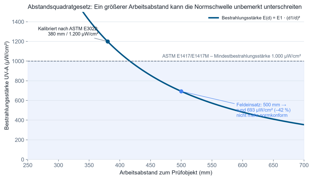
1. Assumptions. A UV-A LED hand lamp was certified by the manufacturer per ASTM E3022 at the reference distance of 380 mm (15 inches) with an irradiance of 1,200 µW/cm². In practical field inspection on a large structural part, the actual working distance increases to 500 mm.
2. Model. For a point source, the inverse square law applies: E2 = E1 · (d1/d2)².
3. Calculation. E2 = 1200 µW/cm² · (380/500)² = 1200 · 0.578 ≈ 693 µW/cm².
4. Result. The actual irradiance at the part drops to around 693 µW/cm² – below the minimum irradiance of 1,000 µW/cm² required by ASTM E1417/E1417M.
5. Technical interpretation. A lamp certified as norm-compliant can be operated in the field, unnoticed, below the normative threshold through an inconspicuous working distance around 30 percent larger. The calibration certificate states something about the source under defined conditions – not about the actual irradiance at the real inspection point. A shift-start check with a radiometer positioned at the part is therefore the only method that reliably reveals this effect.
Where is UV technology used in aerospace?
In engine manufacturing and overhaul (MRO), fluorescent penetrant inspection is established for turbine blades and rotating components because that is where the finest surface-breaking fatigue cracks form under cyclic thermomechanical load, invisible to the naked eye; the critical process variable is uniform irradiance across complex, curved geometries including internal cooling passages. In landing gear and structural fabrication, the method serves to detect fatigue cracks on highly stressed metallic fittings; here the reproducibility of inspection conditions across many repeat inspections over the part's life cycle is critical. For optical and sensor assemblies – such as star trackers, camera optics or mirror systems – photochemical cleaning with UVC and ozone is used because mechanical or wet-chemical processes would risk particle contamination or damage on sensitive optical surfaces; it is described under Surface cleaning and surface activation with UVC and ozone, with the BS-OX available as the corresponding device; here the limiting factor is that the cleaning effect only reaches near-surface organic contamination. In space material qualification – thermal control coatings, multi-layer insulation film, solar cell cover glass – UV and VUV irradiation is one of several partial stresses tested together with vacuum, thermal cycling and particle radiation per ECSS-Q-ST-70-71C – see also UV aging, color fastness and photostability for background; the critical factor here is the spectral match of the test source to the real solar spectrum outside Earth's atmosphere (AM0).
What do MRO handheld lamps, 172 nm excimer sources and combined space rigs deliver?
For mobile field inspection in the MRO environment, battery-powered UV-A LED hand-held lamps have become established, whose discharge behavior must be documented per ASTM E3022 down to the point where output falls below 1,000 µW/cm² – relevant for continuous shift use. For cleaning particularly sensitive, mercury-free process environments, xenon excimer lamps with VUV emission at 172 nm are increasingly used; they generate reactive oxygen without mercury and with comparatively low thermal load on the sample (Fraunhofer IFAM). For a more realistic space simulation, combined test rigs exist that join UV irradiation with thermal vacuum and, in some cases, particle bombardment in a single facility; individual irradiation chambers always reproduce only the optical partial stress and are combined with other test rigs – the dose a single chamber delivers over a given operating time can be estimated in advance with the UV Chamber Irradiance Calculator.
Which quantities need to be measured or monitored?
The starting point of any quality assurance process is which physical quantity is needed at which location – not which measuring instrument happens to be available. For FPI, the relevant quantity is the UV-A irradiance at the actual inspection point, measured with a calibrated radiometer filtered to the UV-A range (320–400 nm) such as the RMD Pro, since a spectrally unfiltered measurement or one taken at the wrong location does not allow a norm-compliant statement. For photochemical cleaning, UVC irradiance and process time are additionally relevant. For material aging tests, a spectrally resolved measurement of the source is often needed – for example with a spectroradiometer such as the SR900 – since it is the match of the spectral distribution to the real solar or reference spectrum, not just the integral power, that determines whether the test results are transferable. A broadband measurement is sufficient for routine shift checks on a known, already characterized source; a spectral measurement becomes necessary as soon as a new lamp is qualified, a source type is changed, or the spectral match of an irradiation chamber to a reference spectrum must be demonstrated. Spatially resolved measurements are required for large or geometrically complex parts to capture shadowing effects; time-resolved measurements become relevant for mercury-vapor lamps because of warm-up drift and for aging LED sources because of lumen decline over their service life. Measurement uncertainties arise, among other things, from the sensor's cosine angular response, thermal drift and the traceability of the calibration to an accredited standard.
In automated FPI inspection cells, inline UV-A sensors are cyclically read out to provide a documented, traceable irradiance record at the inspection point for every inspection run – the technical basis for audits under Nadcap criteria (AC7114), which require seamless process documentation, not just a one-off annual calibration. In irradiation chambers for material aging, continuous spectral monitoring of the source allows automated readjustment when lamp aging causes the spectral distribution or total output to drift, keeping dose constant over long test periods rather than specified only at the start of the test. Digitally connecting such sensor data to a process control system is not an end in itself, but the only practical way to actually detect the deviations described in the section “What limits the process” – warm-up drift, aging, distance errors – during operation, rather than only suspecting them after a missed indication.
What do customer scientific publications show?
The current scientific point of connection for aerospace applications lies mainly in astrobiology, not in industrial aviation manufacturing itself: customers use the BS-02 irradiation chamber to simulate UV and UVC exposure on simulated Martian regolith. Three recent papers from this work:
Davis, G. M., Greenhill, A. R., Munro, T. W., Horner, J., Marsden, S. C., Carter, B. D. (2025). Partial protection of Bacillus subtilis spores on simulated Martian media enhances survival against UV radiation. Discover Space, 129(1). DOI: 10.1007/s11038-025-09563-1.
Arribas Tiemblo, M., Rayo, P., Martín-Redondo, M.-P., Gómez, F. (2025). Effects of Mineralogy and UV Radiation on the Detectability of Amino Acids Within the Martian Regolith: The Case for a Combined Chromatographical and Spectroscopical Approach. Journal of Geophysical Research: Planets, 130(11). DOI: 10.1029/2025JE009070.
Davis, G. M., et al. (2026). Bacillus subtilis endospore integrity and viability on simulated Martian regolith in rotational UVC radiation exposures. Life Sciences in Space Research, 50, 146–152. DOI: 10.1016/j.lssr.2026.01.008.
All three papers demonstrate the use of UV and UVC irradiation technology in astrobiology, not in industrial aviation manufacturing – a narrow but credible point of connection. Further use cases by subject area are listed in the overview Publications by customers – by topic.
The publication finder lists all publications on aerospace we know of – searchable by device, field and keyword.
Technical background and further sources
- ASTM International – E1417/E1417M-21, Standard Practice for Liquid Penetrant Testing; E2297, Standard Guide for Use of UV-A and Visible Light Sources and Meters; E3022, Standard Practice for Measurement of Emission Characteristics and Requirements for LED UV-A Lamps. Summarized via ASTM technical overview (Magnaflux) and standard text excerpt.
- National Aerospace Standard NAS 410 Rev. 5 (2020) – Certification & Qualification of Nondestructive Test Personnel, and SAE AMS 2644 – Inspection Material, Penetrant. See NAS 410 overview and AMS 2644 overview.
- ECSS – European Cooperation for Space Standardization: ECSS-Q-ST-70-71C, Space Product Assurance – Materials, Processes and Their Data Selection (document); ECSS-Q-ST-70-06C, Particle and UV Radiation Testing for Space Materials (document).
- Boeing, Commercial Market Outlook 2026 (Boeing, 2026).
- Strategic Market Research, Aerospace NDT Market and Fluorescent Penetrant Inspection Market – commercial market studies, used as supplementary sources (Aerospace NDT report, FPI report).
- Peer-reviewed literature on UV effects in the space context: Davis et al. (2025), Discover Space, DOI 10.1007/s11038-025-09563-1; Davis et al. (2026), Life Sciences in Space Research, DOI 10.1016/j.lssr.2026.01.008; Arribas Tiemblo et al. (2025), JGR Planets, DOI 10.1029/2025JE009070; Miyazaki & Yui (2021), CEAS Space Journal, atomic oxygen erosion.
FAQ on UV technology in aerospace
How does fluorescent crack detection on turbine blades work?
A penetrant is drawn by capillary action into surface-breaking cracks, wiped from the surface, then drawn back out by a developer. Under UV-A excitation, the dye fluoresces visibly against a dark background, making sub-visual cracks appear as a clear indication.
What irradiance is required for FPI?
ASTM E1417/E1417M requires a minimum irradiance of 1,000 µW/cm² UV-A, measured directly on the surface being inspected – not at the lamp housing or at the manufacturer's calibration distance.
What is the difference between mercury-vapor and LED UV-A lamps?
Mercury-vapor lamps need a warm-up time to reach stable output and emit a line spectrum around 365 nm; LED lamps deliver instant stability with a narrower spectral distribution but are subject to lumen decline over their service life, which must be verified per ASTM E3022.
Why is a UV irradiation chamber not a complete space simulation?
An irradiation chamber reproduces only the optical stress. Vacuum, thermal cycling, atomic oxygen and particle radiation are missing; a credible simulation combines several specialized test rigs per ECSS-Q-ST-70-71C.
How is photochemical surface cleaning with UVC and ozone measured?
The relevant quantities are the UVC irradiance of the source and the process time; since the effect only reaches near-surface organic layers, measuring the source characteristics themselves – not just the optical end result – is required.
Why is a time value alone not always sufficient to dose UV exposure?
Dose is physically the product of irradiance and time (Bunsen-Roscoe law). However, this reciprocity principle does not hold unconditionally; a documented reciprocity failure is known for several polymers, meaning that the same calculated dose does not necessarily produce the same aging effect.
Which standard governs the qualification of NDT inspection personnel in aviation?
NAS 410 sets the minimum requirements for training, experience and certification of personnel performing non-destructive testing methods such as FPI in the aerospace industry.
Which technology is suitable for characterizing a UV aging test source?
Since the spectral match to the reference spectrum determines the transferability of results, a spectrally resolving measurement of the source is required – an integral broadband measurement alone does not show a spectral mismatch.
Related application fields
These applications are closely related, technically, to adjacent fields of optical radiation metrology – for example Fluorescent Penetrant Testing & Industrial Inspection (comparable inspection materials and excitation requirements), Optics & Precision Components (comparable requirements for optical clarity and surface cleanliness), Electronics & Semiconductor Industry (comparable cleanroom and surface processes), and Automotive & Vehicle Components (comparable normative requirements for process documentation).
Author: Dr. Mark Paravia
Dr.-Ing. Mark Paravia is the managing director of Opsytec Dr. Gröbel GmbH in Ettlingen and heads the accredited calibration laboratory. Following his research on pulsed xenon excimer discharges at the Institute of Lighting Technology at KIT, his current focus is on optical radiation measurement technology. He is vice-chair of the DIN Standards Committee FNL 7 “Optical Radiation,” and a member of the DVGW Project Group on UV Disinfection.
Is the actual irradiance still reaching the part or the test chamber?
Unsure whether the irradiance actually reaching the part or the test chamber meets the normative requirement? A measurement at the real inspection point – not at the manufacturer's reference point – provides clarity. For field inspection at FPI stations, the RMD Pro is suitable; for the spectral characterization of sources in irradiation chambers, the SR900. Get in touch about your inspection or process task.