Calibrated measurement of the spectrum, irradiance and luminous flux of LEDs – from the UV to the near infrared.
LED measurement technology – measuring irradiance, spectrum and luminous flux
Depending on the measurement task, LED meters record the irradiance, the spectrum, the radiant flux or the luminous flux of an LED. For reproducible results, the measured quantity, spectral range, measurement geometry and calibration must be matched to the application.
Opsytec offers calibrated LED measurement technology for UV, visible and NIR LEDs: the SR900 spectroradiometer, the RMD Pro and RMD Touch radiometers with calibrated radiometer sensors, and custom integrating spheres. They characterise single LEDs as well as LED modules and LED systems.
How do you measure an LED?
The choice of measurement method depends on the physical quantity. Calibrated radiometers are used for irradiance. To determine the spectral distribution of an LED, a spectroradiometer is required. The total radiant flux or luminous flux is measured with an integrating sphere in combination with a spectroradiometer.
Besides the measured quantity, the spectral range, measuring distance, angle of incidence and calibration all affect the result. Especially with narrow-band UV LEDs, the spectral responsivity of the sensor must match the emission wavelength. For comparable results, the measurement geometry should be kept constant and documented in a traceable way.
Which quantities matter for LEDs?
Which quantity is needed depends on the application. The table assigns the appropriate measuring instrument and typical applications to each quantity:
| Quantity | Unit | Measuring instrument | Typical application |
|---|---|---|---|
| Spectral irradiance | W/(m²·nm) | SR900 with cosine diffuser or radiometric measuring head | LED characterisation, photobiological assessment |
| Irradiance | W/m², mW/cm² | RMD Pro or RMD Touch with sensor; SR900 | UV curing, UV bonding, disinfection |
| UV dose | J/m², mJ/cm² | RMD Pro or RMD Touch with sensor | Process monitoring, exposure |
| Illuminance | lx | RMD Pro or RMD Touch with LUX sensor; SR900 | Lighting, test stations |
| Radiant flux (radiant power) | W | SR900 with integrating sphere | UV and NIR LEDs, efficiency |
| Spectral radiant flux | W/nm | SR900 with integrating sphere | Development, binning |
| Luminous flux | lm | SR900 with integrating sphere | Visible LEDs and LED modules |
| Peak wavelength, dominant wavelength, full width at half maximum | nm | SR900 | Quality and incoming inspection |
| Chromaticity, correlated colour temperature | x, y; K | SR900 | Lighting technology, colour consistency |
| Weighted quantities, e.g. erythema or PPFD | W/m², µmol/(m²·s) | SR900 with action spectra in SRpro | Plant lighting, UV exposure |
For pure process control, a calibrated radiometer is often sufficient. Complete spectral characterisation requires a spectroradiometer. When which method is adequate is compared in the article Spectroradiometer or broadband radiometer.
Measuring the LED spectrum
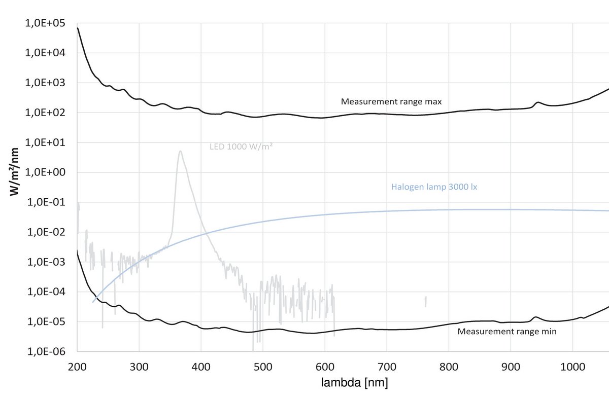
The emission spectrum of an LED describes the spectral distribution of the emitted radiation. A spectroradiometer determines the peak wavelength, spectral bandwidth and spectral irradiance from it.
The SR900 spectroradiometer measures optical radiation from 200 to 1100 nm and is therefore suitable for UV LEDs, visible LEDs and many NIR light sources. The spectral measurement assesses an LED far more accurately than a broadband sensor when the emission wavelength changes or several spectral components are present. Spectral changes, shifts of the peak wavelength and differences between LED batches become directly visible.
For visible LEDs, the SRpro software also calculates photometric and colorimetric quantities from the spectrum, such as chromaticity, dominant wavelength and correlated colour temperature.
Typical applications are:
- Development of LEDs and LED modules
- Quality control
- Incoming inspection
- Ageing studies
- Temperature tests
- Characterisation of UV LEDs
- Colour measurement
- Plant lighting
- Photobiological studies
Measuring LED irradiance
Irradiance describes the optical radiant power incident on a surface and is expressed in W/m² or mW/cm². In many industrial applications, this absolute quantity – not the complete spectrum – is what matters.
This applies, for example, to UV curing, UV bonding, exposure, disinfection and photochemical processes. For in-process and recurring control measurements, the RMD Pro and RMD Touch radiometers are used with spectrally suitable sensors; both measure irradiance and dose on two sensor inputs. For reproducible results, the measuring distance, angle of incidence and sensor position must remain constant.
The radiometer sensors are available in seven spectral ranges: UVC (200–280 nm), UVB (280–315 nm), UVA (315–400 nm), UVA+ (330–455 nm), UVBB (230–400 nm), VISB (400–480 nm) and LUX (380–780 nm, V(λ)-weighted). Calibrated measuring heads enable reproducible measurements in the laboratory and in production environments.
Measuring the luminous flux and radiant flux of LEDs
LEDs often have a pronounced spatial radiation pattern. A measurement in a single direction therefore does not fully capture the total optical power emitted.
An integrating sphere captures the total optical flux of an LED. For visible LEDs it is stated as luminous flux in lumens; for UV and NIR LEDs, the radiant flux in watts is the relevant quantity. Combined with a spectroradiometer, the sphere measures angle-integrated and thus independently of the radiation pattern – so even LEDs with strongly directional or complex spatial emission can be compared.
For this purpose, the SR900 can be combined with Opsytec integrating spheres. How luminous flux, luminance and chromaticity are related for LEDs and displays is explained in more depth on the page Lighting technology, LED & display technology.
Measuring UV LEDs at 365, 385, 395 and 405 nm
With UV LEDs, the spectral range of the sensor must match the actual emission. In the short-wave range, the spectral mismatch of a broadband radiometer can noticeably distort the result; in the transition between UVA and visible light, the filter edge of the sensor can.
The UVA LEDs common in industry emit at 365, 385, 395 and 405 nm with a full width at half maximum of about 10 to 16 nm. The UVA sensor ends at 400 nm. In measured spectra from the Opsytec spectral database, around 95 % of the radiant power of a 385 nm LED lies below 400 nm, only about 70 % for a 395 nm LED and just under 30 % for a 405 nm LED. Even small shifts of the peak wavelength caused by temperature or current then change the reading considerably. Opsytec therefore recommends the UVA+ sensor with 330–455 nm for UV LEDs from 365 to 405 nm, as it captures the entire emission.
Alternatively, the SR900 assesses the LED spectrally from 200 nm, independently of a filter characteristic. This is particularly advantageous when LED batches, ageing effects or temperature-related wavelength shifts are investigated. For production and control measurements, calibrated UVC, UVB, UVA and UVA+ sensors are available.
If the radiant flux of UV LEDs is to be measured in an integrating sphere, the wavelength determines the coating: below 300 nm, the reflectance of barium sulphate drops, and PTFE is the only coating with a usable reflectance there. The technology, efficiency and lifetime of UV LEDs are described in the article UV LEDs for UVA, UVB and UVC.
Measuring visible LEDs
With visible LEDs, photometric and colorimetric parameters are often of interest in addition to radiometric quantities.
Depending on the measurement set-up, the spectral measurement determines colour coordinates, colour temperature and photometric quantities, among others. The photobiological assessment, for example of the blue light hazard to EN 62471, is also based on the measured spectrum – more on this under Occupational safety and photobiological safety. For the illuminance of white LEDs, a lux meter with a V(λ)-weighted sensor is often sufficient.
Combined with an integrating sphere, the total light output of an LED, an LED module or a compact luminaire can be captured.
Light sources compared: halogen lamp, fluorescent lamp and LED
How much light a lamp produces from one watt of electrical power is stated in the data sheet as luminous efficacy in lm/W. The comparison uses typical data sheet values of a halogen lamp, a fluorescent lamp and an LED lamp at equal electrical power; the values can be overwritten. The measured spectra from the Opsytec spectral database yield the chromaticity, correlated colour temperature, colour rendering index Ra and the share of electrical power emitted as visible radiation. The selection also includes the reference spectra of typical fluorescent lamps and LEDs to CIE 015:2018. For each lamp type, the status under the RoHS Directive is shown.
LED meters and measuring systems
Depending on the quantity and application, different measuring systems are used: the SR900 for spectrum, peak wavelength, spectral irradiance and colorimetric quantities; RMD Pro and RMD Touch for irradiance and dose in process, laboratory and quality assurance; the radiometer sensors for the appropriate spectral range; and the integrating sphere for luminous flux and radiant flux of visible, UV and NIR LEDs.
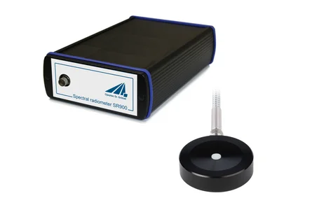
SR900
Array spectroradiometer for 200 to 1100 nm with integrating spheres, cosine diffuser and probes as accessories.

Radiometer RMD Pro
All-digital handheld radiometer for irradiance and dose with two sensor inputs and 8 GB memory.
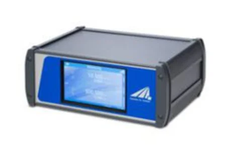
RMD Touch
Digital laboratory radiometer with touch display for irradiance and dose on two sensor inputs.
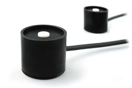
Radiometer sensors
Interchangeable UV and light sensors Ø 40 mm in seven spectral ranges for RMD Pro, RMD Touch and RM-12.
LED measuring systems for laboratory and industry
LED measurement tasks range from simple intensity checks to complete spectral and spatially integrated characterisation. By combining radiometer, spectroradiometer, light guide, measuring head and integrating sphere, the measuring system is adapted to the specific LED, geometry and measured quantity.
The measuring systems are calibrated for defined spectral ranges, traceable to the PTB; a DAkkS-accredited calibration is carried out by the Opsytec calibration laboratory. Traceable calibrations and documented measurement conditions are the basis for comparable results in development, quality assurance and industrial process control.
Frequently asked questions about LED measurement
Which meter is suitable for which LED measurement?
For irradiance at a measurement plane, for example in UV curing or disinfection, a calibrated radiometer such as the RMD Pro or RMD Touch with a sensor for the appropriate spectral range is sufficient. Spectrum, peak wavelength, dominant wavelength, chromaticity and colour temperature require a spectroradiometer such as the SR900. The SR900 measures the total luminous flux or radiant flux of an LED in combination with an integrating sphere, because only the sphere captures the radiation from all emission directions.
Can LEDs be measured with a lux meter?
Yes, if illuminance is required and the LED emits white or broadband light. A lux meter weights the light with a sensor modelled on the luminous efficiency curve V(λ). With coloured, narrow-band LEDs, any deviation between sensor and V(λ) at the emission wavelength has its full effect on the reading; there, the spectral measurement with the SR900 is more accurate. A lux meter is unsuitable for UV LEDs because V(λ) is zero below 380 nm; UV radiation is measured with a radiometer or spectroradiometer. A lux meter does not measure the luminous flux in lumens – that requires an integrating sphere.
Which spectral range suits UV LEDs from 365 to 405 nm?
For UV LEDs Opsytec recommends the UVA+ range of 330–455 nm. The classic UVA sensor ends at 400 nm; a 395 or 405 nm LED then sits with part of its emission on the filter edge, and small shifts of the peak wavelength due to temperature or current change the reading noticeably. The UVA+ range captures the entire LED emission and makes the measurement insensitive to such shifts.
How do you measure the power of an LED?
With an LED, a distinction must be made between electrical and optical power. The electrical power is the product of current and voltage. The optical power is measured as radiant flux in watts and, for visible LEDs, additionally as luminous flux in lumens – with an integrating sphere that captures the radiation from all emission directions. The ratio of radiant flux to electrical power is the efficiency of the LED. How much light different lamps produce from one watt of electrical power is shown by the lamp comparison on this page.
Why is the calibration of an LED meter important?
Calibration establishes the relationship between the sensor signal and the physical quantity. For LEDs it must match the source spectrally, because narrow-band emission reacts sensitively to deviations in the spectral responsivity of the sensor. Opsytec calibrates traceably to the PTB and, on request, in the calibration laboratory accredited to ISO/IEC 17025.
Choosing the right LED measuring system
The choice of a suitable LED measuring system depends on the measured quantity, wavelength range, measurement geometry and the required measurement uncertainty. On this basis, we put together the right combination of radiometer, spectroradiometer, sensor and integrating sphere. Describe your measurement task to us – single LED, module or luminaire, the quantity you are looking for and the place of use.
Author: Dr. Mark Paravia
Dr.-Ing. Mark Paravia is the managing director of Opsytec Dr. Gröbel GmbH in Ettlingen and heads the accredited calibration laboratory. Following his research on pulsed xenon excimer discharges at the Institute of Lighting Technology at KIT, his focus today is optical radiation measurement. He is vice-chair of the DIN standards committee FNL 7 “Optical radiation” and a member of the DVGW project group on UV disinfection.