


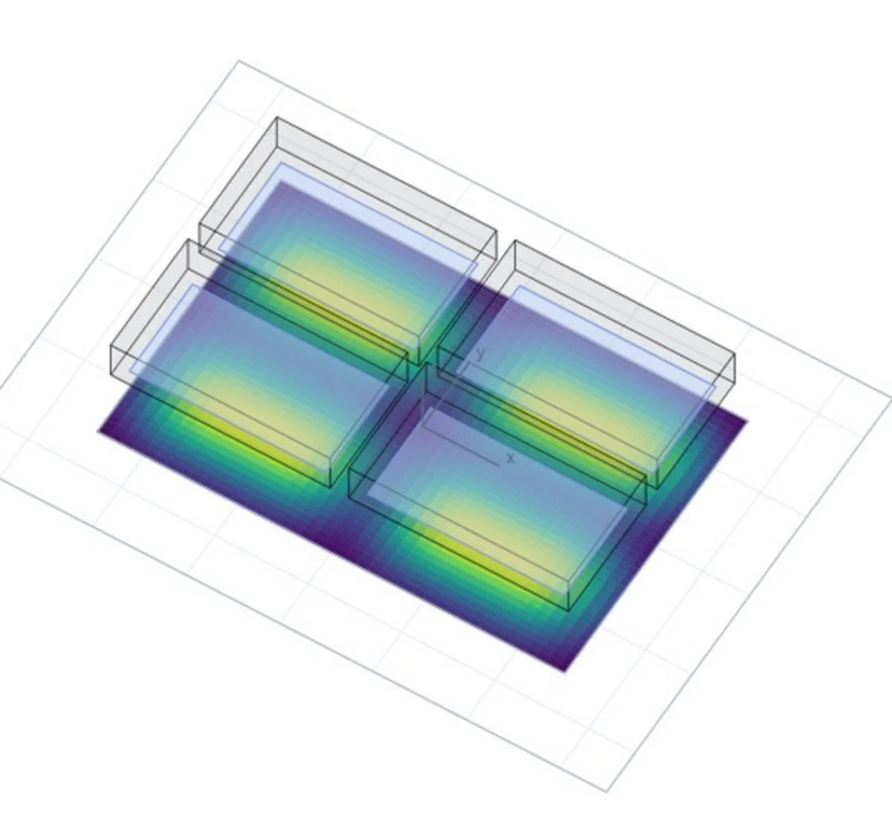
With this simulation by Opsytec Dr. Gröbel you calculate the irradiance (mW/cm²) of large irradiated areas lit jointly by several UV LED luminaires of the SFL and Series L ranges – directly in your browser. Arrange the luminaires as a row, a grid, a ring or freely via a table, rotate and tilt them, and instantly get the distribution on the target surface as a heat map, a 3D view and cross-section profiles – with uniformity, homogeneity and an A/B comparison of two variants.
The calculation uses the same model as the UV LED 3D irradiance calculator (measured emission characteristic of the LED, sum over all LEDs). In addition, the simulation takes shadowing by neighbouring housings into account for tilted luminaires. Results can be exported as CSV, a DXF top view and a PDF simulation report. The calculated values are indicative data for system design; binding irradiance levels should be verified by measurement, e.g. with an Opsytec radiometer.
Model: sum over all LEDs of all luminaires with measured emission characteristic (E = Σ I₀·rel(θ)·cos ε / r²), as in the UV LED 3D irradiance calculator, extended by shadowing from the housings of neighbouring luminaires. Working distance from the front face; the overall area is flat at z = 0. No reflections; manufacturing tolerances, LED spread and temperature effects are not included – indicative values, not measurements.
Model and assumptions of the large-area simulation
Each luminaire consists of its LED array (rows × columns, pitch 10 mm). For every point of the target surface the contribution of every single LED of all luminaires is summed up (photometric inverse-square law):
Formula: E = Σ I₀ · rel(θ) · cos ε / r²
θ is the angle to the axis of the respective luminaire (tilted for tilted luminaires), ε the angle of incidence on the target surface, r the distance. rel(θ) is the measured emission characteristic of the LED, I₀ follows from the radiant flux per LED. In the near field each LED enters as a 3.5 mm die with five sub-sources. For a single, vertical luminaire the result is identical to the UV LED 3D irradiance calculator.
All luminaires of an arrangement are identical (product, wavelength, LED power). Row and grid place the housings next to each other with the selected gap (0 = butt-joined); the ring places the housing centres on the ring radius. Tilting pivots about the centre of the front face; the working distance is measured from the front face to the target surface.
Each housing is a box with the product dimensions above the front face. If the line of sight from an LED to the target point hits the housing of another luminaire, its contribution is dropped. Vertical luminaires with a common front plane cannot shadow each other; the test is skipped in that case.
- Indicative simulation – manufacturing tolerances, LED spread/binning and temperature effects are not included
- No reflections from housings, target or surroundings, no scattering
- Housings as simple boxes; cooling fins, cables and brackets are not considered
- Below 10 mm working distance, die geometry, lens and housing dominate – the calculation is blocked there
- For CAD models the local angle of incidence is taken into account, shadowing by the model itself is not
Frequently asked questions about the large-area simulation
The simulation sums the contributions of all LEDs with the measured emission characteristic and provides indicative values for product selection and system design. For a single luminaire it matches the UV LED 3D irradiance calculator. Manufacturing tolerances, LED spread and binning, temperature effects and reflections from housings and surroundings are not included. Binding irradiance levels should be determined by measurement with a calibrated UV radiometer.
The 3D calculator considers a single luminaire or a freely configurable LED array. This simulation arranges several identical luminaires – as a row, an n × m grid, a ring or freely via a table, rotated and tilted – and takes into account that the housings of neighbouring luminaires can shadow light. The model of the individual LED is the same in both tools.
For row and grid you enter the gap between the housings; 0 mm means butt-joined. For the ring you set the radius on which the housing centres lie and choose whether the long side is oriented tangentially or radially. Overlapping housings are marked red in the 3D view and the top view. The working distance is measured from the front face to the target surface.
When luminaires are tilted, the housing of one luminaire can block the line of sight between an LED of the neighbouring luminaire and the target point. The simulation checks each of these lines of sight against the housings as simple boxes; blocked contributions are dropped. Vertical luminaires with a common front plane do not shadow each other. The check can be switched off under “Calculation & display”.
The key figures show uniformity (min/max) and homogeneity ((max − min)/(max + min)) on the target surface. With “Store as A” and “Store as B” you compare two variants side by side. For row, grid and ring, the optimiser searches for the combination of tilt towards the centre, gap or ring radius and working distance with the best uniformity, without overlapping housings.
You can choose the SFL-UV-M, SFL-UV-L and SFL-UV-XL area lights and the Series L in the sizes XS, XS-HO, S, M and L; the calculation covers wavelengths from 265 to 450 nm. Results can be exported as CSV (grid and cross-section profiles), the arrangement as PNG and DXF and the overall result as a PDF simulation report; the configuration can be shared as a link. STEP and STL models are processed exclusively locally in the browser.
Author: Dr. Mark Paravia
Dr.-Ing. Mark Paravia is the managing director of Opsytec Dr. Gröbel GmbH in Ettlingen and heads the accredited calibration laboratory. Following his research on pulsed xenon excimer discharges at the Institute of Lighting Technology at KIT, his current focus is on optical radiation measurement technology. He is vice-chair of the DIN Standards Committee FNL 7 “Optical Radiation,” and a member of the DVGW Project Group on UV Disinfection.