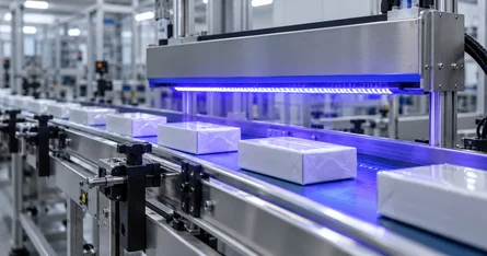
In a continuous process the result is not decided by the cycle time but by the time a point on the workpiece actually spends under the source. This calculator derives that dwell time from belt speed and irradiated length, the dose from it – and conversely the highest speed at which a required dose is still reached.
This is the calculation behind every conveyor line: the coating supplier specifies a dose, the line has a fixed irradiated length, and the feed rate is what you are looking for. Running the line faster lowers the dose in the same proportion; doubling the speed halves it. The same calculation shows whether an additional emitter is needed to reach a desired throughput at all.
The calculation assumes irradiance is uniform along the irradiated length. Real emitters have a profile peaking in the middle – what counts then is the integral over the pass, which a travelling dosimeter measures directly. Opsytec manufactures and calibrates these instruments in its own laboratory.
The static calculation without belt motion is in the UV dose calculator and the UV exposure time calculator; all twelve radiometric calculators are collected in the radiometry calculator.
This calculation is for technical orientation. It applies to an irradiance that is uniform along the irradiated length and to a constant belt speed. Process releases must be verified by a measurement with calibrated instruments under real conditions – in a continuous process, sensibly with a travelling dosimeter.
Fundamentals
Dwell time is the irradiated length divided by the belt speed: t = L / v. The dose follows as in the static case: H = E · t. Rearranging both for speed gives the highest speed for a target dose: v_max = L · E / H_target. The calculator takes the length in millimetres and the speed in metres per minute — the units used in production — and converts to SI internally; from L in mm and v in m/min, t in seconds follows via the factor 0.06.
An emitter irradiates 200 mm of the belt, the line runs at 6 m/min. t = 200 mm ÷ 6 m/min = 2 s. At 500 mW/cm² this gives H = 500 · 2 = 1000 mJ/cm². For the same target dose of 1000 mJ/cm² the belt may therefore run at no more than 6 m/min; at 500 mJ/cm² it could run at 12 m/min.
Irradiance is rarely constant along the pass — it rises towards the middle of the emitter and falls off at the edges. The product E · t then overestimates the dose if the peak value is used and underestimates it with the edge value. Several emitters in series add their contributions, not their lengths. And as always: dose is an energetic quantity and says nothing about whether the spectrum matches the photoinitiator.
Frequently asked questions
First the dwell time from irradiated length and belt speed, then the dose from irradiance and dwell time: t = L / v and H = E · t. At 200 mm and 6 m/min that is 2 s; with 500 mW/cm² it gives 1000 mJ/cm².
The distance along the belt direction over which a point on the workpiece is actually irradiated — not the physical length of the emitter housing. With several emitters in series each section counts separately; the dose contributions add up.
Inversely proportional: double the speed means half the dwell time and therefore half the dose. Doubling the throughput requires double the irradiance or double the irradiated length.
Usually because of the emitter profile: the calculation assumes uniform irradiance, while in reality the workpiece passes through a maximum. Add to that changes in distance from workpiece height, a dirty window and ageing of the source. How strongly a source declines is shown in ageing of UV lamps and UV LEDs.
A travelling dosimeter for process release and a permanently installed sensor for ongoing monitoring. The measuring practice is described in UV measurement for conveyor systems.
Yes, with the same approach: belt speed is replaced by the path speed of the tool, and irradiated length by the irradiated path length. Applications are described under robotics.
Author: Dr. Mark Paravia
Dr.-Ing. Mark Paravia is the managing director of Opsytec Dr. Gröbel GmbH in Ettlingen and heads the accredited calibration laboratory. Following his research on pulsed xenon excimer discharges at the Institute of Lighting Technology at KIT, his current focus is on optical radiation measurement technology. He is vice-chair of the DIN Standards Committee FNL 7 “Optical Radiation” and a member of the DVGW Project Group on UV Disinfection.